SFI SYSTEM(w/o Canister Pump Module), Diagnostic DTC:P023A12, P023A13, P023A14
| DTC Code | DTC Name |
|---|---|
| P023A12 | Charge Air Cooler Coolant Pump Control Circuit Short to Battery |
| P023A13 | Charge Air Cooler Coolant Pump Control Circuit Open |
| P023A14 | Charge Air Cooler Coolant Pump Control Circuit Short to Ground or Open |
DESCRIPTION
The intercooler cooling system is a water cooling system that is independent from the engine cooling system. It uses a dedicated radiator and electric water pump assembly to cool the intercooler and turbocharger. The electric water pump assembly uses the duty cycle signals sent from the ECM to provide stepless, optimal control of the electric water pump assembly speed.
| DTC No. | Detection Item | DTC Detection Condition | Trouble Area | MIL | Memory | Note |
|---|---|---|---|---|---|---|
| P023A12 | Charge Air Cooler Coolant Pump Control Circuit Short to Battery | Electric water pump assembly output voltage is specified value or higher (1 trip detection logic). |
|
- | DTC stored | SAE: P023C |
| P023A13 | Charge Air Cooler Coolant Pump Control Circuit Open | Electric water pump assembly speed is less than 10 rpm (1 trip detection logic). |
|
- | DTC stored | SAE: P023A |
| P023A14 | Charge Air Cooler Coolant Pump Control Circuit Short to Ground or Open | Electric water pump assembly output voltage is specified value or less (1 trip detection logic). |
|
- | DTC stored | SAE: P023B |
MONITOR DESCRIPTION
If the electric water pump assembly speed is below 10 rpm when it is being driven, the ECM evaluates a malfunction and stores the DTC P023A13.
The electric water pump assembly operates steplessly according to duty cycle signals from the ECM. The ECM monitors the current value of the electric water pump assembly. When the actual drive duty cycle ratio deviates from the target drive duty cycle, the ECM detects a malfunction and stores P023A12 or P023A14.
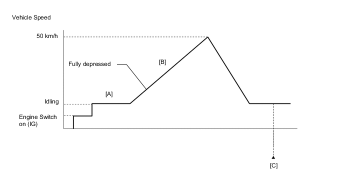
CONFIRMATION DRIVING PATTERN
-
Connect the GTS to the DLC3.
-
Turn the engine switch on (IG) and turn the GTS on.
-
Clear the DTCs (even if no DTCs are stored, perform the clear DTC procedure).
-
Turn the engine switch off and wait for at least 30 seconds.
-
Turn the engine switch on (IG) and turn the GTS on.
-
Start the engine and warm it up until the engine coolant temperature reaches 75°C (167°F) or higher [A].
-
Accelerate to 50 km/h (31 mph) or more with the accelerator pedal fully depressed [B].
CAUTION:
When performing the confirmation driving pattern, obey all speed limits and traffic laws.
-
Enter the following menus: Powertrain / Engine / Trouble Codes [C].
-
Read the pending DTCs.
Tech Tips
-
If a pending DTC is output, the system is malfunctioning.
-
If a pending DTC is not output, perform the following procedure.
-
-
Enter the following menus: Powertrain / Engine / Utility / All Readiness.
-
Input the DTC: P023A12, P023A13 or P023A14.
-
Check the DTC judgment result.
GTS Display Description NORMAL
-
DTC judgment completed
-
System normal
ABNORMAL
-
DTC judgment completed
-
System abnormal
INCOMPLETE
-
DTC judgment not completed
-
Perform driving pattern after confirming DTC enabling conditions
N/A
-
Unable to perform DTC judgment
-
Number of DTCs which do not fulfill DTC preconditions has reached ECU memory limit
Tech Tips
-
If the judgment result shows NORMAL, the system is normal.
-
If the judgment result shows ABNORMAL, the system has a malfunction.
-
If the judgment result shows INCOMPLETE or N/A, perform steps [B] through [C] again.
-
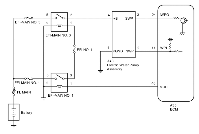
WIRING DIAGRAM
CAUTION / NOTICE / HINT
Note
Inspect the fuses for circuits related to this system before performing the following procedure.
Tech Tips
Read freeze frame data using the GTS. The ECM records vehicle and driving condition information as freeze frame data the moment a DTC is stored. When troubleshooting, freeze frame data can help determine if the vehicle was moving or stationary, if the engine was warmed up or not, if the air fuel ratio was lean or rich, and other data from the time the malfunction occurred.
PROCEDURE
-
PERFORM ACTIVE TEST USING GTS (CONTROL THE INTERCOOLER WATER PUMP)
-
Connect the GTS to the DLC3.
-
Turn the engine switch on (IG).
-
Turn the GTS on.
-
Enter the following menus: Powertrain / Engine / Active Test / Control the Intercooler Water Pump.
Powertrain > Engine > Active TestTester Display Control the Intercooler Water Pump -
Perform the Active Test. Check that the electric water pump assembly is operating (vibrating).
OK The electric water pump assembly is operating (vibrating). Tech Tips
Use a sound scope if the operation is difficult to check.
Result Proceed to OK NG
NG 
CHECK TERMINAL VOLTAGE (POWER SOURCE OF ELECTRIC WATER PUMP ASSEMBLY) Click here
OK 
-
-
CHECK HARNESS AND CONNECTOR (ELECTRIC WATER PUMP ASSEMBLY - ECM)
-
Disconnect the electric water pump assembly connector.
-
Disconnect the ECM connector.
-
Measure the resistance according to the value(s) in the table below.
Standard Resistance Tester Connection Condition Specified Condition A43-2 (NWP) - A35-11 (IWPI) Always Below 1 Ω A43-3 (SWP) - A35-24 (IWPO) Always Below 1 Ω A43-2 (NWP) or A35-11 (IWPI) - Body ground and other terminals Always 10 kΩ or higher A43-3 (SWP) or A35-24 (IWPO) - Body ground and other terminals Always 10 kΩ or higher Result Proceed to OK NG
NG 
REPAIR OR REPLACE HARNESS OR CONNECTOR
OK
-
-
CHECK ECM (IWPI VOLTAGE)
-
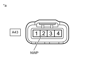
*a Front view of wire harness connector
(to Electric Water Pump Assembly)
Disconnect the electric water pump assembly connector.
-
Turn the engine switch on (IG).
-
Measure the voltage according to the value(s) in the table below.
Standard Voltage Tester Connection Switch Condition Specified Condition A43-2 (NWP) - Body ground Engine switch on (IG) 11 to 14 V Result Proceed to OK NG
OK
REPLACE ELECTRIC WATER PUMP ASSEMBLY Click here
NG
REPLACE ECM Click here
-
-
CHECK TERMINAL VOLTAGE (POWER SOURCE OF ELECTRIC WATER PUMP ASSEMBLY)
-
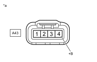
*a Front view of wire harness connector
(to Electric Water Pump Assembly)
Disconnect the electric water pump assembly connector.
-
Turn the engine switch on (IG).
-
Measure the voltage according to the value(s) in the table below.
Standard Voltage Tester Connection Switch Condition Specified Condition A43-4 (+B) - Body ground Engine switch on (IG) 11 to 14 V Result Proceed to OK NG
NG
CHECK HARNESS AND CONNECTOR (EFI-MAIN NO. 3 RELAY - ELECTRIC WATER PUMP ASSEMBLY) Click here
OK
-
-
CHECK HARNESS AND CONNECTOR (ELECTRIC WATER PUMP ASSEMBLY - BODY GROUND)
-
Disconnect the electric water pump assembly connector.
-
Measure the resistance according to the value(s) in the table below.
Standard Resistance Tester Connection Condition Specified Condition A43-1 (PGND) - Body ground Always Below 1 Ω Result Proceed to OK NG
NG
REPAIR OR REPLACE HARNESS OR CONNECTOR
OK
-
-
CHECK HARNESS AND CONNECTOR (ELECTRIC WATER PUMP ASSEMBLY - ECM)
-
Disconnect the electric water pump assembly connector.
-
Disconnect the ECM connector.
-
Measure the resistance according to the value(s) in the table below.
Standard Resistance Tester Connection Condition Specified Condition A43-2 (NWP) - A35-11 (IWPI) Always Below 1 Ω A43-3 (SWP) - A35-24 (IWPO) Always Below 1 Ω A43-2 (NWP) or A35-11 (IWPI) - Body ground and other terminals Always 10 kΩ or higher A43-3 (SWP) or A35-24 (IWPO) - Body ground and other terminals Always 10 kΩ or higher Result Proceed to OK NG
NG
REPAIR OR REPLACE HARNESS OR CONNECTOR
OK
-
-
REPLACE ELECTRIC WATER PUMP ASSEMBLY
-
Replace the electric water pump assembly.
Result Proceed to NEXT
NEXT
-
-
CHECK WHETHER DTC OUTPUT RECURS (DTC P023A12, P023A13 OR P023A14)
-
Connect the GTS to the DLC3.
-
Turn the engine switch on (IG).
-
Turn the GTS on.
-
Clear the DTCs.
Powertrain > Engine > Clear DTCs -
Turn the engine switch off and wait for at least 30 seconds.
-
Start the engine and warm it up.
-
Turn the GTS on.
-
Drive the vehicle in accordance with the driving pattern described in Confirmation Driving Pattern.
-
Enter the following menus: Powertrain / Engine / Utility / All Readiness.
Powertrain > Engine > UtilityTester Display All Readiness -
Input the DTC: P023A12, P023A13 or P023A14.
-
Check the DTC judgment result.
Result Result Proceed to NORMAL
(DTCs are not output)
A ABNORMAL
(DTC P023A12, P023A13 or P023A14 is output)
B
A
END
B
REPLACE ECM Click here
-
-
CHECK HARNESS AND CONNECTOR (EFI-MAIN NO. 3 RELAY - ELECTRIC WATER PUMP ASSEMBLY)
-
Remove the EFI-MAIN NO. 3 relay from the No. 1 engine room relay block and junction block assembly.
-
Disconnect the electric water pump assembly connector.
-
Measure the resistance according to the value(s) in the table below.
Standard Resistance Tester Connection Condition Specified Condition 3 (EFI-MAIN NO. 3 relay) - A43-4 (+B) Always Below 1 Ω 3 (EFI-MAIN NO. 3 relay) or A43-4 (+B) - Body ground and other terminals Always 10 kΩ or higher Result Proceed to OK NG
NG
REPAIR OR REPLACE HARNESS OR CONNECTOR
OK
-
-
INSPECT EFI-MAIN NO. 3 RELAY
-
Inspect the EFI-MAIN No. 3 relay.
Result Proceed to OK NG
NG
REPLACE EFI-MAIN NO. 3 RELAY
OK
-
-
CHECK TERMINAL VOLTAGE (POWER SOURCE OF EFI-MAIN NO. 3 RELAY)
-
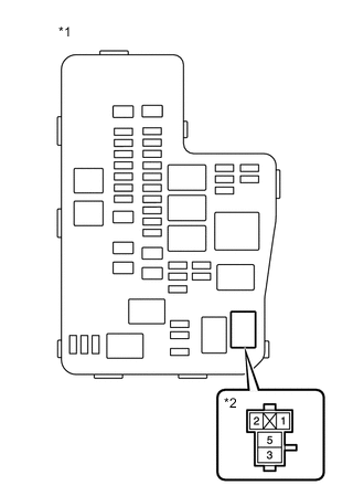
*1 No. 1 Engine Room Relay Block and Junction Block Assembly *2 EFI-MAIN NO. 3 Relay Remove the EFI-MAIN NO. 3 relay from the No. 1 engine room relay block and junction block assembly.
-
Measure the voltage according to the value(s) in the table below.
Standard Voltage Tester Connection Condition Specified Condition 5 (EFI-MAIN NO. 3 relay) - Body ground Always 11 to 14 V Result Proceed to OK NG
NG
REPAIR OR REPLACE HARNESS OR CONNECTOR (EFI-MAIN NO. 3 RELAY - BATTERY)
OK
-
-
CHECK HARNESS AND CONNECTOR (EFI-MAIN NO. 3 RELAY - BODY GROUND)
-
Remove the EFI-MAIN NO. 3 relay from the No. 1 engine room relay block and junction block assembly.
-
Measure the resistance according to the value(s) in the table below.
Standard Resistance Tester Connection Condition Specified Condition 2 (EFI-MAIN NO. 3 relay) - Body ground Always Below 1 Ω Result Proceed to OK NG
OK
REPAIR OR REPLACE HARNESS OR CONNECTOR (EFI-MAIN NO. 3 RELAY - EFI-MAIN NO. 1 RELAY)
NG
REPAIR OR REPLACE HARNESS OR CONNECTOR
-