REAR SPEED SENSOR(for 4WD/AWD) INSTALLATION
CAUTION / NOTICE / HINT
Use the same procedure for the RH and LH sides.
The procedures listed below are for the LH side.
PROCEDURE
INSTALL REAR SPEED SENSOR LH
Note:To prevent interference with other parts, do not twist the sensor wire's painted line areas when installing it.
-
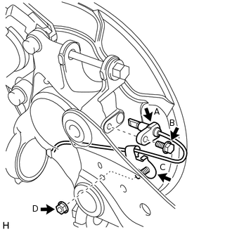
Install the sensor labeled A with the bolt labeled B.
8.5 N*m
87 kgf*cm
75 in.*lbf
Note:Keep the sensor tip and sensor installation hole free from foreign matter.
To prevent interference with the bearing rotor, do not rotate the sensor body when inserting the sensor body or after inserting the sensor body.
Install the sensor clamp labeled C with the nut labeled D.
5.0 N*m
51 kgf*cm
44 in.*lbf
-
*a
Painted Line
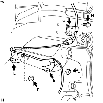
Install the sensor clamps labeled E with the 2 nuts labeled F.
5.0 N*m
51 kgf*cm
44 in.*lbf
Note:Do not twist the sensor wire when installing the clamps.
Install the sensor clamp labeled G with the bolt labeled H.
8.5 N*m
87 kgf*cm
75 in.*lbf
Note:Do not twist the sensor wire when installing the clamp.
-
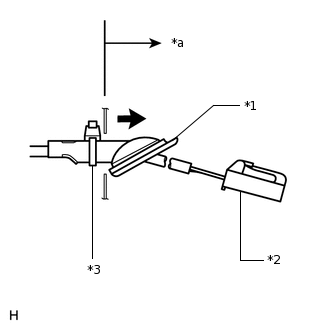
*1
Grommet
*2
Connector
*3
Band Clamp
*a
Inside of Vehicle
Insert the connector and grommet to the inside of the vehicle through the passage hole in the wheel house.
Note:Make sure the grommet band clamp remains on the outside of the vehicle.
Hold the grommet and pull it from the inside of the vehicle to the outside of the vehicle. Then fix it in place so that it is not tilted.
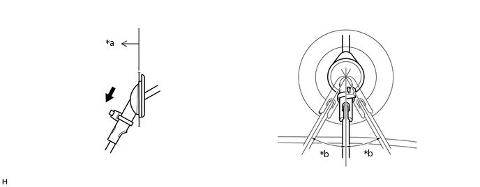
*a
Outside of Vehicle
*b
30°
Note:When pulling out the grommet, do not grip the sensor wire.
Fix the grommet in place within the range shown in the illustration.
Connect the speed sensor connector.
-
INSTALL DECK TRIM SIDE PANEL ASSEMBLY LH
Tip:Refer to the procedures from the installation of the deck trim side panel LH up until the installation of the rear door scuff plate LH.
INSTALL REAR WHEEL
103 N*m
1050 kgf*cm
76 ft.*lbf
CHECK SPEED SENSOR SIGNAL