CHARGING SYSTEM, Diagnostic DTC:P1550,P1551 and P1552
| DTC Code | DTC Name |
|---|---|
| P1550 | Battery Current Sensor Circuit |
| P1551 | Battery Current Sensor Circuit Low |
| P1552 | Battery Current Sensor Circuit High |
DESCRIPTION
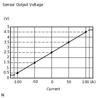
The battery current sensor assembly detects the battery charge and discharge current amount.
The battery current sensor assembly changes this information into a voltage signal and outputs it to the ECM.
Based on this signal, the ECM sends power generation voltage commands to the generator.
DTC No. |
Detection Item |
DTC Detection Condition |
Trouble Area |
MIL |
Memory |
|---|---|---|---|---|---|
P1550 |
Battery Current Sensor Circuit |
Difference between the maximum and minimum current values of the battery current sensor is less than 1 A for 10 seconds or more (1 trip detection logic) |
|
Does not come on |
DTC stored |
P1551 |
Battery Current Sensor Circuit Low |
Battery current sensor output value is abnormally low for 0.5 seconds or more with the ignition switch ON (1 trip detection logic) |
|
Does not come on |
DTC stored |
P1552 |
Battery Current Sensor Circuit High |
Battery current sensor output value is abnormally high for 0.5 seconds or more with the ignition switch ON (1 trip detection logic) |
|
Does not come on |
DTC stored |
WIRING DIAGRAM
Refer to DTC P0516 and P0517.
PROCEDURE
CHECK ANY OTHER DTCS OUTPUT (IN ADDITION TO DTC P1550, P1551 OR P1552)
Connect the GTS to the DLC3.
Turn the ignition switch to ON.
Turn the GTS on.
Enter the following menus: Powertrain / Engine and ECT / Trouble Codes.
Read the DTCs.
Powertrain > Engine > Trouble Codes
Result
Proceed to
DTC P1550, P1551 or P1552 is output
DTC P1550, P1551 or P1552 and other DTCs are output
Tip:If any DTCs other than P1550, P1551 or P1552 are output, troubleshoot those DTCs first.
READ VALUE USING GTS (BATTERY CURRENT)
Turn all of the electrical systems (headlights, blower motor, rear defogger, etc.) off.
Connect the GTS to the DLC3.
Turn the ignition switch to ON.
Turn the GTS on.
Enter the following menus: Powertrain / Engine and ECT / Data List / Battery Current.
Powertrain > Engine > Data List
Tester Display
Battery Current
Result
Result
Proceed to
Battery current is fixed at 0 A, or fluctuates by 1 A or less between -100 and 100 A
A
Battery current fluctuates between -20 and 0 A
B
INSPECT BATTERY CURRENT SENSOR ASSEMBLY
Inspect the battery current sensor assembly.
Result
Result
OK
NG
CHECK HARNESS AND CONNECTOR (BATTERY CURRENT SENSOR ASSEMBLY - ECM)
Disconnect the B76 ECM connector.
Disconnect the B72 battery current sensor assembly connector.
Measure the resistance according to the value(s) in the table below.
Standard Resistance (Check for Open)
Tester Connection
Condition
Specified Condition
B76-77 (EIB) - B72-4 (E2)
Always
Below 1 Ω
B76-75 (VCIB) - B72-2 (VC5)
Always
Below 1 Ω
B76-116 (IB) - B72-3 (IB)
Always
Below 1 Ω
Standard Resistance (Check for Short)
Tester Connection
Condition
Specified Condition
B76-77 (EIB) or B72-4 (E2) - Body ground
Always
10 kΩ or higher
B76-75 (VCIB) or B72-2 (VC5) - Body ground
Always
10 kΩ or higher
B76-116 (IB) or B72-3 (IB) - Body ground
Always
10 kΩ or higher
Result
Result
OK
NG
NG REPAIR OR REPLACE HARNESS OR CONNECTOR