BRAKE CONTROL SYSTEM
-
CONSTRUCTION
-
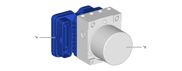
The brake actuator and skid control ECU are integrated into the brake actuator assembly to reduce size and weight.
-
The brake actuator controls the brake fluid pressure of each wheel cylinder and consists of the master cylinder pressure sensor, master cylinder cut solenoid valve, pressure holding solenoid valve, pressure reduction solenoid valve, pump motor, reservoir, etc.
-
The solenoid relay, motor relay and motor cut relay are built into the skid control ECU.
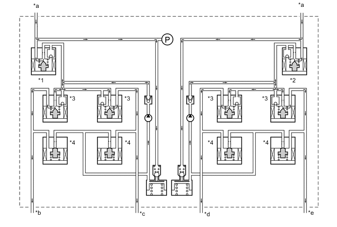
*a Skid Control ECU *b Actuator Portion Figure 1. Hydraulic Circuit (Not Operating)
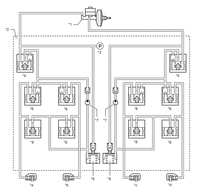
*1 Brake Master Cylinder Sub-assembly *2 Brake Actuator *3 Master Cylinder Pressure Sensor *4 No. 1 Master Cylinder Cut Solenoid Valve *5 No. 2 Master Cylinder Cut Solenoid Valve *6 Pressure Holding Solenoid Valve *7 Pump *8 Pressure Reduction Solenoid Valve *9 Reservoir - - *a Front Brake Caliper RH *b Rear Brake Caliper LH *c Rear Brake Caliper RH *d Front Brake Caliper LH
-
Pressure Holding Solenoid Valve and Pressure Reduction Solenoid Valve
-
The skid control ECU increases, holds or decreases the brake fluid pressure of each wheel cylinder by individually turning its pressure holding solenoid valve and pressure reduction solenoid valve on or off.
-
-
Master Cylinder Cut Solenoid Valve
-
A linear solenoid valve is used for the master cylinder cut solenoid valve, minimizing fluctuations in the brake fluid pressure during control.
-
The master cylinder cut solenoid valve is turned on or off to control the brake fluid pressure from the pump to the wheel cylinder.
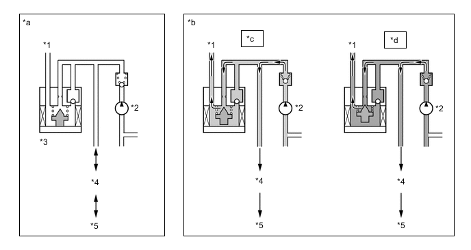
*1 Master Cylinder *2 Pump *3 Master Cylinder Cut Solenoid Valve *4 Pressure Holding Solenoid Valve *5 Brake Caliper - - *a Not Operating *b Operating *c Required Brake Fluid Pressure: Low *d Required Brake Fluid Pressure: High
-
-
Maser Cylinder Pressure Sensor
-
The master cylinder pressure sensor is built into the brake actuator and detects and outputs the brake fluid pressure from the master cylinder to the skid control ECU.
-
-
-
-
OPERATION
-
ABS and EBD
-
The ABS and EBD systems control the pump, pressure holding solenoid valve and pressure reduction valve to control the brake fluid pressure of each wheel cylinder.
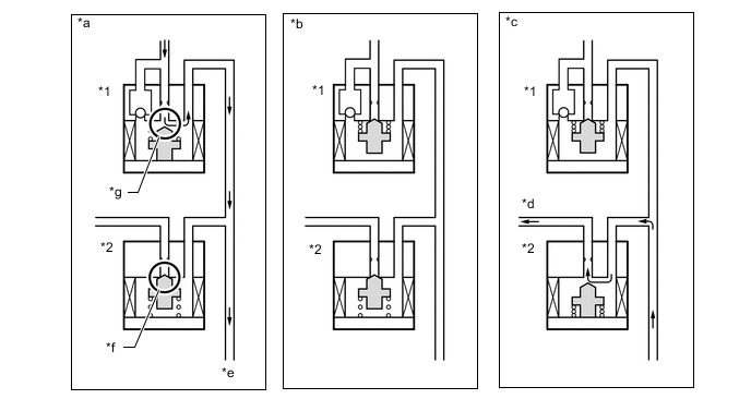
*1 Pressure Holding Solenoid Valve *2 Pressure Reduction Solenoid Valve *a Pressure Increase Mode *b Pressure Holding Mode *c Pressure Reduction Mode *d To Reservoir *e To Brake Caliper *f Port2 *g Port1 - - ABS and EBD Operation Pressure Mode Increase Mode Holding Mode Reduction Mode Pressure Holding Solenoid Valve OFF (Open) ON (Closed) ON (Closed) Pressure Reduction Solenoid Valve OFF (Closed) OFF (Closed) ON (Open) Port1 Open Closed Closed Port2 Closed Closed Open Wheel Cylinder Pressure Increases Holds Reduces
-
-
Brake Assist
-
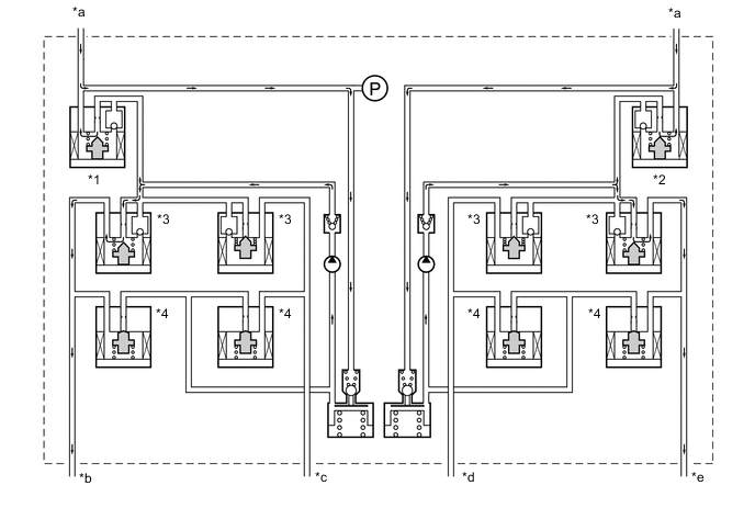
Brake assist controls each pressure holding solenoid valve and pressure reduction solenoid valve to apply brake fluid pressure higher than that of the master cylinder from the pump of the brake actuator to each wheel cylinder.
Figure 2. Hydraulic Circuit
*1 No. 1 Master Cylinder Cut Solenoid Valve *2 No. 2 Master Cylinder Cut Solenoid Valve *3 Pressure Holding Solenoid Valve *4 Pressure Reduction Solenoid Valve *a From Brake Master Cylinder Sub-assembly *b To Front Brake Caliper RH *c To Rear Brake Caliper LH *d To Rear Brake Caliper RH *e To Front Brake Caliper LH - - Brake Assist Operation Brake Assist Not Activated Activated No. 1 Master Cylinder Cut Solenoid Valve OFF (Open) ON* No. 2 Master Cylinder Cut Solenoid Valve OFF (Open) ON* Pressure Holding Solenoid Valve OFF (Open) OFF (Open) Pressure Reduction Solenoid Valve OFF (Closed) OFF (Closed) Wheel Cylinder Pressure Equivalent to Master Cylinder Brake Fluid Pressure Higher Pressure Required than Master Cylinder Brake Fluid Pressure Tech Tips
*: The solenoid valve controls the brake fluid pressure by continually opening and closing the valve in accordance with the operating conditions.
-
-
TRC
-
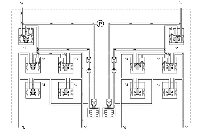
TRC limits the drive force from the engine and controls each pressure holding solenoid valve and pressure reduction solenoid valve to apply more brake fluid pressure from the pump of the brake actuator to the wheel cylinder of each drive wheel to reduce slippage.
Figure 3. Hydraulic Circuit (2WD Models)
*1 No. 1 Master Cylinder Cut Solenoid Valve *2 No. 2 Master Cylinder Cut Solenoid Valve *3 Pressure Holding Solenoid Valve *4 Pressure Reduction Solenoid Valve *a From Brake Master Cylinder Sub-assembly *b To Front Brake Caliper RH *c To Rear Brake Caliper LH *d To Rear Brake Caliper RH *e To Front Brake Caliper LH - - TRC Operation (2WD Models) TRC Not Activated Activated Increase Mode Holding Mode Reduction Mode No. 1 Master Cylinder Cut Solenoid Valve OFF (Open) ON* ON* ON* No. 2 Master Cylinder Cut Solenoid Valve OFF (Open) ON* ON* ON* Front Wheel Pressure Holding Solenoid Valve OFF (Open) OFF (Open) ON (Closed) ON (Closed) Pressure Reduction Solenoid Valve OFF (Closed) OFF (Closed) OFF (Closed) ON (Open) Wheel Cylinder Pressure - Increases Holds Reduces Rear Wheel Pressure Holding Solenoid Valve OFF (Open) ON (Closed) ON (Closed) ON (Closed) Pressure Reduction Solenoid Valve OFF (Closed) OFF (Closed) OFF (Closed) OFF (Closed) Wheel Cylinder Pressure - - - - Tech Tips
*: The solenoid valve controls the brake fluid pressure by continually opening and closing the valve in accordance with the operating conditions.
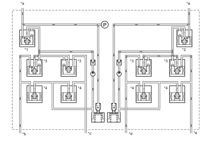
Figure 4. Hydraulic Circuit (AWD Models)

*1 No. 1 Master Cylinder Cut Solenoid Valve *2 No. 2 Master Cylinder Cut Solenoid Valve *3 Pressure Holding Solenoid Valve *4 Pressure Reduction Solenoid Valve *a From Brake Master Cylinder Sub-assembly *b To Front Brake Caliper RH *c To Rear Brake Caliper LH *d To Rear Brake Caliper RH *e To Front Brake Caliper LH - - TRC Operation (AWD Models) TRC Not Activated Activated Increase Mode Holding Mode Reduction Mode No. 1 Master Cylinder Cut Solenoid Valve OFF (Open) ON* ON* ON* No. 2 Master Cylinder Cut Solenoid Valve OFF (Open) ON* ON* ON* Front Wheel Pressure Holding Solenoid Valve OFF (Open) OFF (Open) ON (Closed) ON (Closed) Pressure Reduction Solenoid Valve OFF (Closed) OFF (Closed) OFF (Closed) ON (Open) Wheel Cylinder Pressure - Increases Holds Reduces Rear Wheel Pressure Holding Solenoid Valve OFF (Open) OFF (Open) ON (Closed) ON (Closed) Pressure Reduction Solenoid Valve OFF (Closed) OFF (Closed) OFF (Closed) ON (Open) Wheel Cylinder Pressure - Increases Holds Reduces Tech Tips
*: The solenoid valve controls the brake fluid pressure by continually opening and closing the valve in accordance with the operating conditions.
-
-
VSC (for Oversteer)
-
The VSC system controls the brake fluid pressure of each wheel cylinder in order to control rear wheel skidding.
-
When the vehicle is oversteering while turning to the right, the VSC system controls each pressure holding solenoid valve and pressure reduction valve as shown in the illustration, in order to control rear wheel skidding.
Figure 5. Hydraulic Circuit
*1 No. 1 Master Cylinder Cut Solenoid Valve *2 No. 2 Master Cylinder Cut Solenoid Valve *3 Pressure Holding Solenoid Valve *4 Pressure Reduction Solenoid Valve *a From Brake Master Cylinder Sub-assembly *b To Front Brake Caliper RH *c To Rear Brake Caliper LH *d To Rear Brake Caliper RH *e To Front Brake Caliper LH - - VSC Operation (for Oversteer) VSC Not Activated Activated Increase Mode Holding Mode Reduction Mode No. 1 Master Cylinder Cut Solenoid Valve OFF (Open) ON* ON* ON* No. 2 Master Cylinder Cut Solenoid Valve OFF (Open) ON* ON* ON* Front Wheel RH Pressure Holding Solenoid Valve OFF (Open) ON (Closed) ON (Closed) ON (Closed) Pressure Reduction Solenoid Valve OFF (Closed) OFF (Closed) OFF (Closed) OFF (Closed) Wheel Cylinder Pressure - - - - Front Wheel LH Pressure Holding Solenoid Valve OFF (Open) OFF (Open) ON (Closed) ON (Closed) Pressure Reduction Solenoid Valve OFF (Closed) OFF (Closed) OFF (Closed) ON (Open) Wheel Cylinder Pressure - Increases Holds Reduces Rear Wheel RH Pressure Holding Solenoid Valve OFF (Open) ON (Closed) ON (Closed) ON (Closed) Pressure Reduction Solenoid Valve OFF (Closed) OFF (Closed) OFF (Closed) OFF (Closed) Wheel Cylinder Pressure - - - - Rear Wheel LH Pressure Holding Solenoid Valve OFF (Open) OFF (Open) ON (Closed) ON (Closed) Pressure Reduction Solenoid Valve OFF (Closed) OFF (Closed) OFF (Closed) ON (Open) Wheel Cylinder Pressure - Increases Holds Reduces Tech Tips
*: The solenoid valve controls the brake fluid pressure by continually opening and closing the valve in accordance with the operating conditions.
-
-
VSC (for Understeer)
-
The VSC system controls the brake fluid pressure of each wheel cylinder in order to control front wheel skidding.
-
When the vehicle is understeering while turning to the right, the VSC system controls each pressure holding solenoid valve and pressure reduction valve as shown in the illustration, in order to control front wheel skidding.
Figure 6. Hydraulic Circuit
*1 No. 1 Master Cylinder Cut Solenoid Valve *2 No. 2 Master Cylinder Cut Solenoid Valve *3 Pressure Holding Solenoid Valve *4 Pressure Reduction Solenoid Valve *a From Brake Master Cylinder Sub-assembly *b To Front Brake Caliper RH *c To Rear Brake Caliper LH *d To Rear Brake Caliper RH *e To Front Brake Caliper LH - - VSC Operation (for Understeer) VSC Not Activated Activated Increase Mode Holding Mode Reduction Mode No. 1 Master Cylinder Cut Solenoid Valve OFF (Open) ON* ON* ON* No. 2 Master Cylinder Cut Solenoid Valve OFF (Open) ON* ON* ON* Front Wheel RH Pressure Holding Solenoid Valve OFF (Open) OFF (Open) ON (Closed) ON (Closed) Pressure Reduction Solenoid Valve OFF (Closed) OFF (Closed) OFF (Closed) ON (Open) Wheel Cylinder Pressure - Increases Holds Reduces Front Wheel LH Pressure Holding Solenoid Valve OFF (Open) OFF (Open) ON (Closed) ON (Closed) Pressure Reduction Solenoid Valve OFF (Closed) OFF (Closed) OFF (Closed) ON (Open) Wheel Cylinder Pressure - Increases Holds Reduces Rear Wheel RH Pressure Holding Solenoid Valve OFF (Open) OFF (Open) ON (Closed) ON (Closed) Pressure Reduction Solenoid Valve OFF (Closed) OFF (Closed) OFF (Closed) ON (Open) Wheel Cylinder Pressure - Increases Holds Reduces Rear Wheel LH Pressure Holding Solenoid Valve OFF (Open) ON (Closed) ON (Closed) ON (Closed) Pressure Reduction Solenoid Valve OFF (Closed) OFF (Closed) OFF (Closed) OFF (Closed) Wheel Cylinder Pressure - - - - Tech Tips
*: The solenoid valve controls the brake fluid pressure by continually opening and closing the valve in accordance with the operating conditions.
-
-
Hill-start Assist Control
-
Hill-start assist control temporarily maintains the brake fluid pressure of all 4 wheels to prevent the vehicle from rolling backward.
Figure 7. Hill-start Control Operation with the Shift Lever in D (Driver Depresses Accelerator to Start Off)
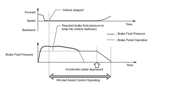
Figure 8. Hill-start Control Operation with the Shift Lever in D (Driver does Nothing)
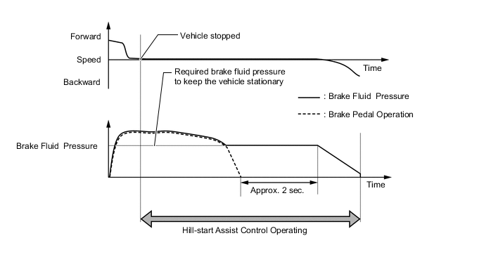
Figure 9. Hydraulic Circuit (Pressure Maintained)
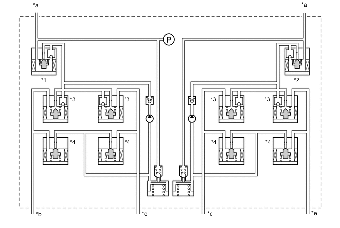
*1 No. 1 Master Cylinder Cut Solenoid Valve *2 No. 2 Master Cylinder Cut Solenoid Valve *3 Pressure Holding Solenoid Valve *4 Pressure Reduction Solenoid Valve *a From Brake Master Cylinder Sub-assembly *b To Front Brake Caliper RH *c To Rear Brake Caliper LH *d To Rear Brake Caliper RH *e To Front Brake Caliper LH - - Hill-assist Control Operation Hill-assist Control Not Activated Activated Holding Mode Reduction Mode No. 1 Master Cylinder Cut Solenoid Valve OFF (Open) ON (Closed) OFF (Open) No. 2 Master Cylinder Cut Solenoid Valve OFF (Open) ON (Closed) OFF (Open) Front Wheel Pressure Holding Solenoid Valve OFF (Open) OFF (Open) OFF (Open) Pressure Reduction Solenoid Valve OFF (Closed) OFF (Closed) OFF (Closed) Wheel Cylinder Pressure - Holds Reduces Rear Wheel Pressure Holding Solenoid Valve OFF (Open) OFF (Open) OFF (Open) Pressure Reduction Solenoid Valve OFF (Closed) OFF (Closed) OFF (Closed) Wheel Cylinder Pressure - Holds Reduces
-
-
Brake Hold
-
The brake hold function maintains the brake fluid pressure of all 4 wheels to keep the vehicle stationary.
Figure 10. Brake Hold Operation (Driver Depresses Accelerator to Start Off)
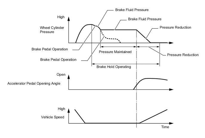
Figure 11. Hydraulic Circuit

*1 No. 1 Master Cylinder Cut Solenoid Valve *2 No. 2 Master Cylinder Cut Solenoid Valve *3 Pressure Holding Solenoid Valve *4 Pressure Reduction Solenoid Valve *a From Brake Master Cylinder Sub-assembly *b To Front Brake Caliper RH *c To Rear Brake Caliper LH *d To Rear Brake Caliper RH *e To Front Brake Caliper LH - - Brake Hold Operation Brake Hold Not Activated Activated Holding Mode Reduction Mode No. 1 Master Cylinder Cut Solenoid Valve OFF (Open) ON (Closed) OFF (Open) No. 2 Master Cylinder Cut Solenoid Valve OFF (Open) ON (Closed) OFF (Open) Front Wheel Pressure Holding Solenoid Valve OFF (Open) OFF (Open) OFF (Open) Pressure Reduction Solenoid Valve OFF (Closed) OFF (Closed) OFF (Closed) Wheel Cylinder Pressure - Holds Reduces Rear Wheel Pressure Holding Solenoid Valve OFF (Open) OFF (Open) OFF (Open) Pressure Reduction Solenoid Valve OFF (Closed) OFF (Closed) OFF (Closed) Wheel Cylinder Pressure - Holds Reduces
-
-