REAR STABILIZER BAR INSTALLATION
PROCEDURE
INSTALL REAR STABILIZER BUSHING
-
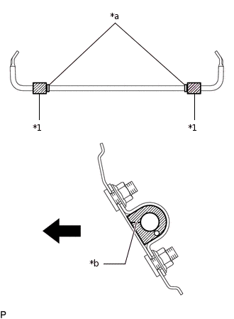
*1
Rear Stabilizer Bushing
*a
Bushing Stopper
*b
Rear Stabilizer Bushing Slit

Front of the Vehicle
Install the 2 rear stabilizer bushings to the rear stabilizer bar on the outside of the bush stoppers as shown in the illustration.
Note:Install the rear stabilizer bushing so that the bushing stopper of the rear stabilizer bar is facing the vehicle interior.
Install the rear stabilizer bushing so that the slit is in the position shown in the illustration.
-
INSTALL REAR STABILIZER BAR
-
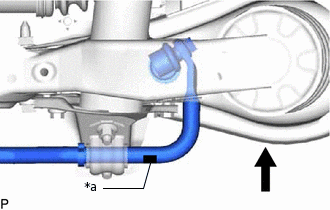
*a
Paint Mark
Front of the Vehicle
Install the rear stabilizer bar so that the paint mark is facing the right side of the vehicle.
-
INSTALL REAR NO. 1 STABILIZER BAR BRACKET
-
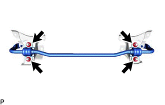
Install the 2 rear No. 1 stabilizer bar brackets to the rear stabilizer support bracket with the 4 nuts.
60 N*m
612 kgf*cm
44 ft.*lbf
-
INSTALL REAR STABILIZER SUPPORT BRACKET
-
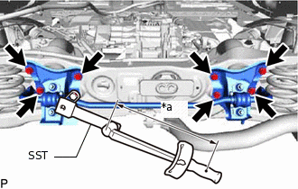
*a
Torque Wrench Fulcrum Length
Using SST, install the rear stabilizer support bracket LH and rear stabilizer support bracket RH to the rear suspension member sub-assembly with the 8 bolts.
Specified tightening torque
50 N*m
510 kgf*cm
37 ft.*lbf
Tip:Calculate the torque wrench reading when changing the fulcrum length of the torque wrench.
When using SST (fulcrum length of 150 mm (5.906 in.)) + torque wrench (fulcrum length of 255 mm (10.039 in.)): 31.5 N*m (321 kgf*cm, 23 ft.*lbf)
-
INSTALL REAR STABILIZER LINK ASSEMBLY LH
Note:Since the rear stabilizer link assembly LH, 2 rear stabilizer cushions and nut (B) are not reusable, new parts must be installed.
-
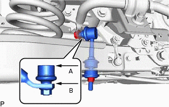
Nut (A)

Nut (B)
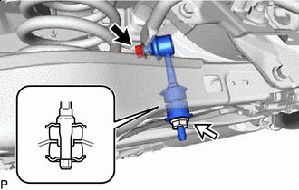
Install a new rear stabilizer link assembly LH and 2 new rear stabilizer cushions to the rear No. 2 suspension arm assembly with a new nut (B) as shown in the illustration.
30 N*m
306 kgf*cm
22 ft.*lbf
Note:Be sure to install the rear stabilizer cushions in the correct direction as shown in the illustration.
Install the rear stabilizer link assembly LH to the rear stabilizer bar with the nut (A).
74 N*m
755 kgf*cm
55 ft.*lbf
Tip:If the ball joint turns together with the nut, use a 6 mm hexagon wrench to hold the stud.
-
Adjust the rear stabilizer link assembly LH so that A and B are parallel as shown in the illustration.
-
INSTALL REAR STABILIZER LINK ASSEMBLY RH
Tip:Use the same procedure described for the LH side.
INSTALL REAR HEIGHT CONTROL SENSOR SUB-ASSEMBLY LH (w/ Automatic Headlight Beam Level Control System)
INSTALL REAR WHEEL
INSPECT AND ADJUST REAR WHEEL ALIGNMENT