SFI SYSTEM(w/o EGR System) FREEZE FRAME DATA
DESCRIPTION
The ECM records vehicle and driving condition information as freeze frame data the moment a DTC is stored. When troubleshooting, freeze frame data can be helpful in determining whether the vehicle was moving or stationary, whether the engine was warmed up or not, whether the air-fuel ratio was lean or rich, as well as other data recorded at the time of a malfunction.
Freeze frame data records the engine conditions (fuel system information, calculated load, engine coolant temperature, fuel trim, engine speed, vehicle speed, etc.) when a malfunction is detected.
Tip:If it is impossible to duplicate the problem even though a DTC is output, check the freeze frame data.
-
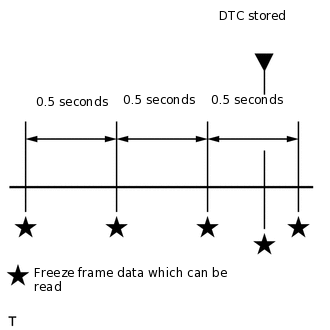
The ECM records engine conditions in the form of freeze frame data every 0.5 seconds. Using the intelligent tester, 5 separate sets of freeze frame data can be checked.
-
3 data sets from before the DTC was stored
1 data set from when the DTC was stored
1 data set from after the DTC was stored
These data sets can be used to simulate the condition of the vehicle from around the time of the occurrence of the malfunction. The data may assist in identifying the cause of the malfunction, and in judging whether it was temporary or not.
LIST OF FREEZE FRAME DATA
Powertrain > Engine and ECT
Tester Display
Vehicle Speed
Engine Speed
Calculate Load
Vehicle Load
MAF
Atmosphere Pressure
Coolant Temp
Intake Air
Engine Run Time
Initial Engine Coolant Temp
Initial Intake Air Temp
Battery Voltage
Glow Indicator Supported
Glow Indicator
Accel Sens. No.1 Volt %
Accel Sens. No.2 Volt %
Throttle Sensor Volt %
Throttl Sensor #2 Volt %
Throttle Sensor Position
Throttle Motor DUTY
Throttle Position
ISC Flow
ISC Position
ISC Feedback Value
ISC Learning Value
Electric Load Feedback Val
Air Conditioner FB Val
PS Feedback Val
Low Revolution Control
Neutral Control
N Range Status
Eng Stall Control FB Flow
Deposit Loss Flow
ISC Feedback Learning Torque
ISC Total AUXS Torque
ISC Feedback Torque
ISC Feedback Torque(Recent)
ISC AUXS Torque(Alternator)
ISC AUXS Torque(Air Conditioner)
Throttle Air Flow F/B Value
Injector (Port)
Injection Volum (Cylinder1)
Fuel Pump/Speed Status
Current Fuel Type
EVAP (Purge) VSV
Evap Purge Flow
Purge Density Learn Value
EVAP Purge VSV
Purge Cut VSV Duty
Target Air-Fuel Ratio
AF Lambda B1S1
AF Lambda B2S1
AFS Voltage B1S1
AFS Voltage B2S1
AFS Current B1S1
AFS Current B2S1
A/F Heater Duty #1
A/F Heater Duty #2
O2S B1S2
O2S B2S2
O2S Impedance B1S2
O2S Impedance B2S2
O2 Heater B1S2
O2 Heater B2S2
O2 Heater Curr Val B1S2
O2 Heater Curr Val B2S2
Short FT #1
Long FT #1
Total FT #1
Short FT #2
Long FT #2
Total FT #2
Fuel System Status #1
Fuel System Status #2
Air Pump Pressure (Absolute)
Air Pump2 Pressure (Absolute)
Air Pump Pulsation Pressure
Secondary Air Control VSV
2nd Air System Status
AI Test
IGN Advance
Knock Feedback Value
Knock Correct Learn Value
Idle Spark Advn Ctrl #1
Idle Spark Advn Ctrl #2
Idle Spark Advn Ctrl #3
Idle Spark Advn Ctrl #4
Idle Spark Advn Ctrl #5
Idle Spark Advn Ctrl #6
Idle Spark Advn Ctrl #7
Idle Spark Advn Ctrl #8
ACIS VSV
Actual VVT Angle #1
Actual VVT Angle #2
Actual VVT Ex Angle #1
Actual VVT Ex Angle #2
VVT Control Status #1
VVT Control Status #2
VVT Advance Fail
Catalyst Temp B1S1
Catalyst Temp B2S1
Catalyst Temp B1S2
Catalyst Temp B2S2
Starter Signal
Power Steering Signal
Neutral Position SW Signal
Transfer L4
Stop Light Switch
A/C Signal
Idle Up Signal
Closed Throttle Position SW
Fuel Cut Condition
Immobiliser Communication
TC Terminal
Time after DTC Cleared
Distance from DTC Cleared
Warmup Cycle Cleared DTC
Dist Batt Cable Disconnect
TC and TE1
Total Distance Traveled
Engine Speed (Starter Off)
Starter Count
Run Dist of Previous Trip
Engine Starting Time
Previous Trip Coolant Temp
Previous Trip Intake Temp
Engine Oil Temperature
Previous Trip Eng Oil Temp
Ambient Temp for A/C
Previous Trip Ambient Temp
Engine Start Hesitation
Low Rev for Eng Start
Minimum Engine Speed
A/F Learn Value Idle #1
A/F Learn Value Low #1
A/F Learn Value Mid1 #1
A/F Learn Value Mid2 #1
A/F Learn Value High #1
A/F Learn Value Idle #2
A/F Learn Value Low #2
A/F Learn Value Mid1 #2
A/F Learn Value Mid2 #2
A/F Learn Value High #2
Power Steering Pressure
ACT VSV
Brake Override System
Idle Fuel Cut
FC TAU
Immobiliser Fuel Cut
Immobiliser Fuel Cut History
Comm with Power Manage
Comm with Air Conditioner
Electrical Load Signal 1
Electrical Load Signal 2
Cruise Cancel Signal
SPD (NT)
SPD (SP2)
Shift SW Status (P Range)
Shift SW Status (R Range)
Shift SW Status (N Range)
Shift SW Status (N,P Range) Supported
Shift SW Status (N,P Range)
Sports Shift Up SW
Sports Shift Down SW
Sports Mode Selection SW
Snow Switch Status
Shift SW Status (D Range)
A/T Oil Temperature 1
A/T Oil Temperature 2
ATF Thermal Degradation Estimate
Lock Up
Shift Status
SLT Solenoid Status
SLU Solenoid Status
Off-road Guidance Status
Snow or 2nd Start Mode