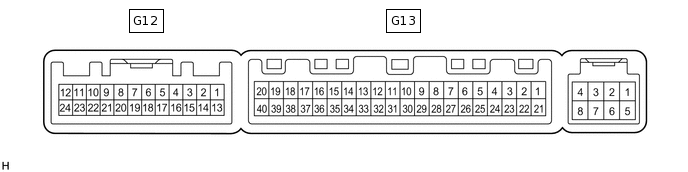
CLIMATE CONTROL SEAT SYSTEM TERMINALS OF ECU
AIR CONDITIONING AMPLIFIER
Measure the voltage and resistance according to the value(s) in the table below.
Terminal No. (Symbol)
Wiring Color
Terminal Description
Condition
Specified Condition
G12-6 (SG-5) - Body ground
R - Body ground
Ground
Always
Below 1 Ω
G12-8 (S5-2) - Body ground
SB - Body ground
Power supply
Engine switch on (IG)
4.5 to 5.5 V
G12-9 (ROUT) - Body ground
LG - Body ground
Output climate control signal (Front passenger side)
Engine switch on (IG)
Refreshing seat switch RH blower side level 3
Pulse generation
(see waveform 1)
G12-10 (LOUT) - Body ground
V - Body ground
Output climate control signal (Driver side)
Engine switch on (IG)
Refreshing seat switch LH blower side level 3
Pulse generation
(see waveform 1)
G12-15 (SW 5) - Body ground
W - Body ground
Input climate control signal (Front passenger side)
Engine switch on (IG)
Refreshing seat switch RH level 0
4.5 to 5.5 V
Engine switch on (IG)
Refreshing seat switch RH blower side level 3
Below 1 V
G12-16 (SW 4) - Body ground
V - Body ground
Input climate control signal (Driver side)
Engine switch on (IG)
Refreshing seat switch LH level 0
4.5 to 5.5 V
Engine switch on (IG)
Refreshing seat switch LH blower side level 3
Below 1 V
G13-31 (S5-4) - Body ground
V - Body ground
Power supply
Engine switch on (IG)
4.5 to 5.5 V
G13-35 (SG-4) - Body ground
G - Body ground
Ground
Always
Below 1 Ω
If the result is not as specified, the air conditioning amplifier may have a malfunction.
-
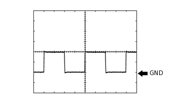
Using an oscilloscope, check waveform 1.
Table 1. Waveform 1 (Reference) Item
Content
Terminal No. (Symbol)
G12-9 (ROUT) - Body ground
G12-10 (LOUT) - Body ground
Tool Setting
2 V/DIV., 500 μsec/DIV.
Condition
Engine switch on (IG)
Refreshing seat switch blower side level 3
-