STEERING COLUMN ASSEMBLY REMOVAL
PROCEDURE
PRECAUTION
ALIGN FRONT WHEELS FACING STRAIGHT AHEAD
REMOVE HORN BUTTON ASSEMBLY
REMOVE STEERING WHEEL ASSEMBLY
REMOVE LOWER STEERING COLUMN COVER
-
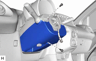
Remove the 3 screws.
-
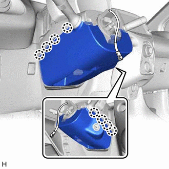
Disengage the 8 claws and remove the lower steering column cover.
-
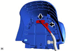
REMOVE UPPER NO. 2 STEERING COLUMN COVER
-
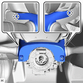
Disengage the 2 claws and remove the upper No. 2 steering column cover.
-
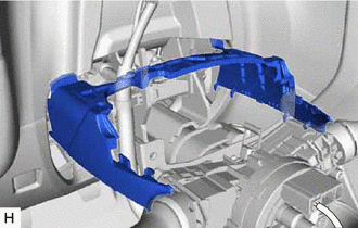
REMOVE COMBINATION METER ASSEMBLY
-
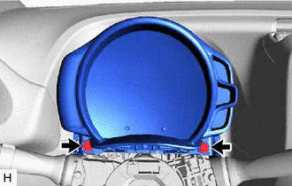
Remove the 2 bolts and separate the combination meter assembly from the steering column assembly.
-
Disconnect the 2 connectors and remove the combination meter assembly.
-
REMOVE UPPER NO. 1 STEERING COLUMN COVER
-
Remove the upper No. 1 steering column cover.
-
REMOVE TURN SIGNAL SWITCH ASSEMBLY WITH SPIRAL CABLE SUB-ASSEMBLY
Note:w/ VSC:
Do not replace the spiral cable with sensor sub-assembly with the battery connected and the ignition switch ON.
Do not rotate the spiral cable with sensor sub-assembly without the steering wheel assembly with the battery connected and the ignition switch ON.
Ensure that the steering wheel assembly is installed and aligned straight when inspecting the steering sensor.
Disconnect each connector from the turn signal switch assembly with spiral cable sub-assembly.
-
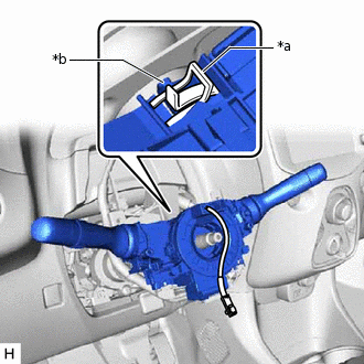
*a
Clamp
*b
Claw
Using pliers, expand the clamp.
While holding the clamp expanded, raise the claw using a screwdriver to disengage it, and then remove the turn signal switch assembly with spiral cable sub-assembly from the steering column assembly.
REMOVE POWER STEERING ECU ASSEMBLY
REMOVE STEERING COLUMN HOLE COVER PLATE
Turn back the floor carpet.
-
Disengage the 2 claws and remove the steering column hole cover plate.
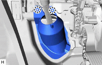
SEPARATE NO. 2 STEERING INTERMEDIATE SHAFT ASSEMBLY
-
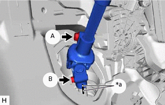
*a
Matchmark
Put matchmarks on the No. 2 steering intermediate shaft assembly and steering gear assembly.
Loosen the bolt (A).
Remove the bolt (B).
Separate the No. 2 steering intermediate shaft assembly from the steering gear assembly.
-
REMOVE NO. 2 STEERING INTERMEDIATE SHAFT ASSEMBLY
-
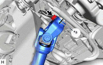
*a
Matchmark
Put matchmarks on the No. 2 steering intermediate shaft assembly and the steering column assembly.
Remove the bolt and No. 2 steering intermediate shaft assembly from the steering column assembly.
-
REMOVE STOP LIGHT SWITCH ASSEMBLY
REMOVE STEERING COLUMN ASSEMBLY
Disconnect each connector and disengage each wire harness clamp from the steering column assembly.
-
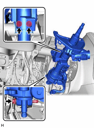
Remove the 3 bolts and steering column assembly.