AUTOMATIC TRANSAXLE UNIT DISASSEMBLY

PROCEDURE
-
REMOVE BREATHER PLUG HOSE
-
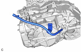
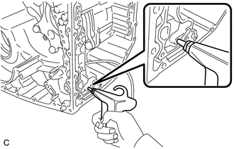
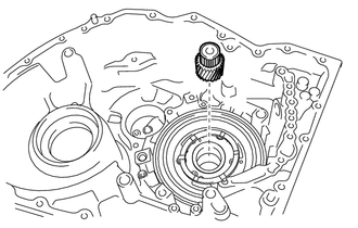
Using a screwdriver with its tip wrapped with protective tape, remove the breather plug hose from the breather plug.
Note
Be careful not to damage the breather plug.
-
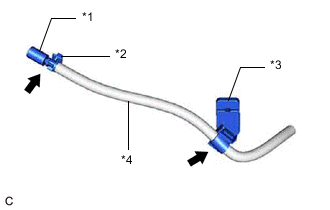
*1 No. 1 Breather Plug (ATM) *2 Breather Hose Clamp *3 Transmission Breather Clamp *4 Breather Plug Hose Using a screwdriver with its tip wrapped with protective tape, remove the No. 1 breather plug (ATM) from the breather plug hose.
Note
Be careful not to damage the No. 1 breather plug (ATM).
-
Remove the breather hose clamp and transmission breather clamp from the breather plug hose.
-
-
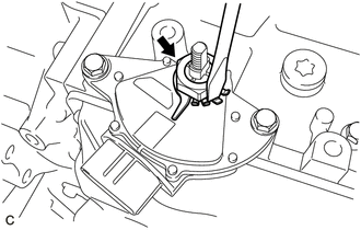
REMOVE TRANSMISSION CONTROL SHAFT LEVER
-
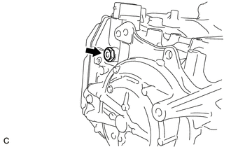
Remove the nut and transmission control shaft lever from the manual valve lever sub-assembly.
-
-
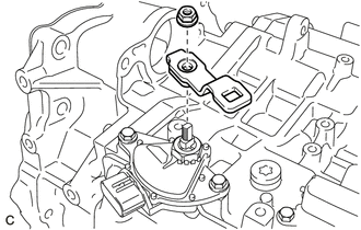
REMOVE PARK/NEUTRAL POSITION SWITCH ASSEMBLY
-
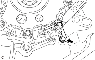
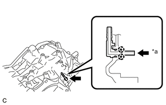
Using a screwdriver, bend back the tabs of the lock plate and remove the lock nut and lock plate from the park/neutral position switch assembly.
-
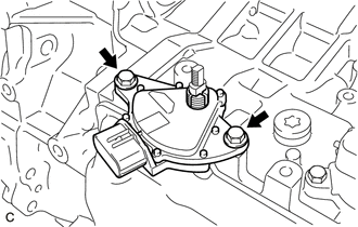
Remove the 2 bolts and park/neutral position switch assembly from the automatic transaxle case sub-assembly.
-
-
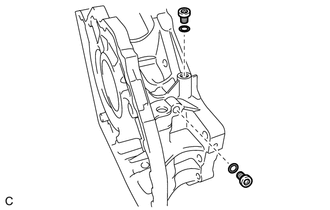
REMOVE DRAIN PLUG
-
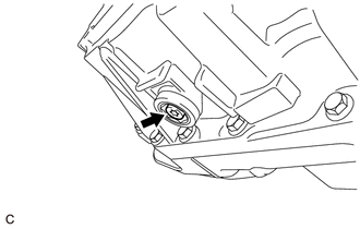
Using a T40 "TORX" socket wrench, remove the drain plug from the overflow plug.
-
Remove the O-ring from the drain plug.
-
-
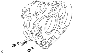
REMOVE OVERFLOW PLUG
-
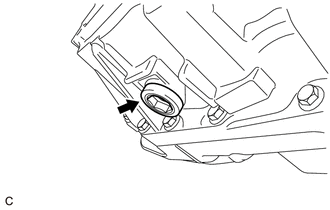
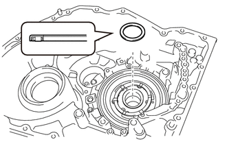
Using a 17 mm straight hexagon wrench, remove the overflow plug from the transaxle housing.
-
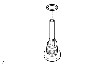
Remove the O-ring from the overflow plug.
-
-
REMOVE OUTLET NO. 1 OIL COOLER TUBE SUB-ASSEMBLY
-
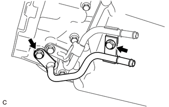
Remove the 2 bolts and outlet No. 1 oil cooler tube sub-assembly from the transaxle housing.
-
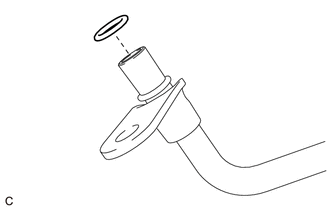
Remove the O-ring from the outlet No. 1 oil cooler tube sub-assembly.
-
-
REMOVE INLET NO. 1 OIL COOLER TUBE SUB-ASSEMBLY
-
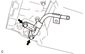
Remove the 2 bolts and inlet No. 1 oil cooler tube sub-assembly from the transaxle housing.
-
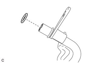
Remove the O-ring from the inlet No. 1 oil cooler tube sub-assembly.
-
-
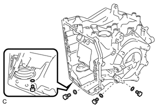
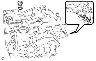
REMOVE REFILL PLUG
-
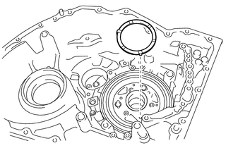
Remove the refill plug from the automatic transaxle case sub-assembly.
-
Remove the gasket from the refill plug.
-
-
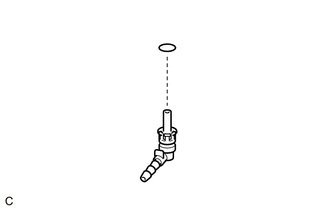
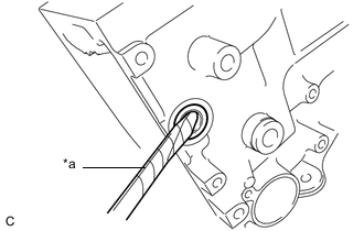
REMOVE TRANSMISSION CASE PLUG ASSEMBLY
-
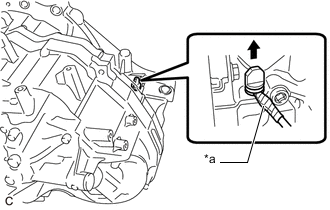
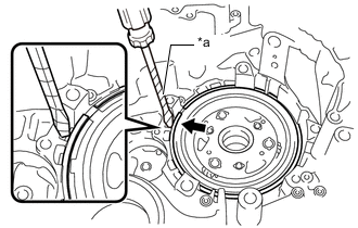
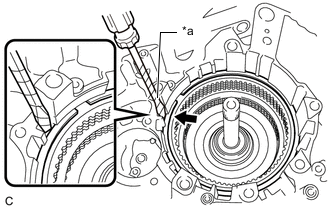
*a Protective Tape Using a screwdriver with its tip wrapped with protective tape, remove the transmission case plug assembly from the transaxle housing.
Note
Be careful not to damage the transaxle housing.
-
-
REMOVE TRANSAXLE SIDE COVER SUB-ASSEMBLY
-
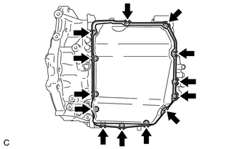
Using a T40 "TORX" socket wrench, remove the 13 bolts.
-
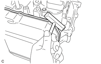
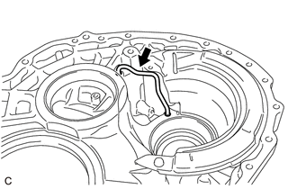
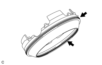
Insert the blade of an oil pan seal cutter between the transaxle side cover sub-assembly and automatic transaxle case sub-assembly. Cut through the applied seal packing and remove the transaxle side cover sub-assembly.
Note
Be careful not to damage the sealing surface of the automatic transaxle case sub-assembly.
-
-
REMOVE TRANSMISSION OIL CLEANER MAGNET
-
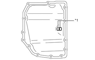
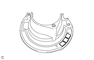
*1 Transmission Oil Cleaner Magnet Remove the 2 transmission oil cleaner magnets from the transaxle side cover sub-assembly.
-
-
REMOVE TRANSMISSION VALVE BODY ASSEMBLY
-
REMOVE TRANSMISSION WIRE
-
REMOVE TRANSMISSION REVOLUTION SENSOR (NC3)
-
REMOVE TRANSMISSION REVOLUTION SENSOR (NT)
-
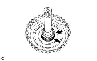
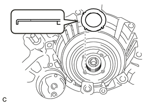
INSPECT INPUT SHAFT END PLAY
-
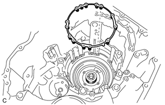
REMOVE TRANSAXLE HOUSING
-
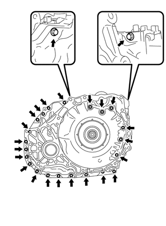
Remove the 24 bolts.
-
Using a plastic hammer, tap on the circumference of the transaxle housing to remove it from the automatic transaxle case sub-assembly.
-
-
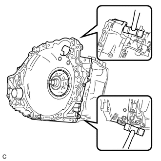
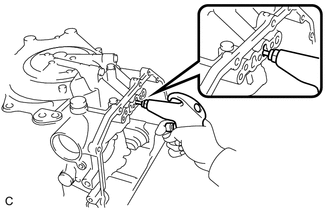
REMOVE DIFFERENTIAL GEAR LUBE APPLY TUBE
-
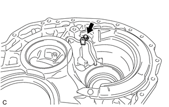
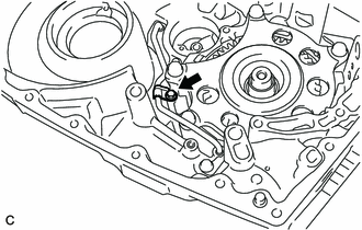
Remove the bolt and clamp from the transaxle housing.
-
Remove the differential gear lube apply tube from the transaxle housing.
-
-
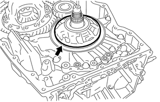
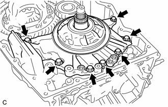
REMOVE TRANSAXLE HOUSING OIL SEPARATOR
-
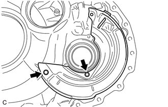
Remove the 2 bolts and transaxle housing oil separator from the transaxle housing.
-
Remove the 3 transmission oil cleaner magnets from the transaxle housing oil separator.
-
-
INSPECT TRANSMISSION OIL CLEANER MAGNET
-
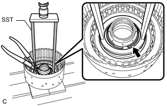
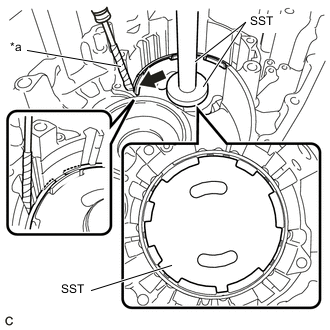
REMOVE DIFFERENTIAL CASE TAPERED ROLLER BEARING (FRONT SIDE OUTER RACE)
-
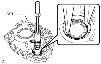
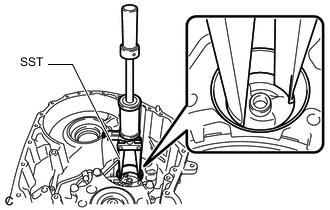
Using SST, remove the differential case tapered roller bearing (front side outer race) from the transaxle housing.
- SST
- 09308-00010
-
-
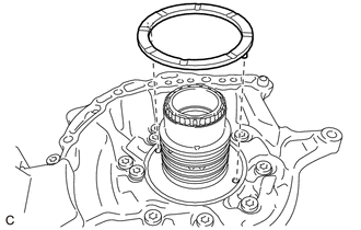
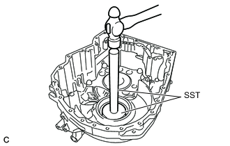
REMOVE TRANSAXLE CASE OIL SEAL
-
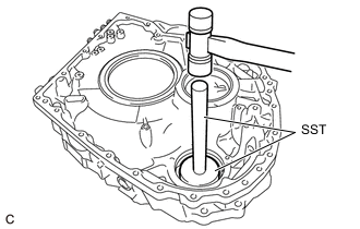
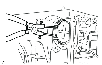
Using SST and a hammer, remove the transaxle case oil seal from the transaxle housing.
- SST
- 09950-60010 ( 09951-00550 )
- 09950-70010 ( 09951-07200 )
-
-
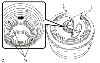
REMOVE COUNTER DRIVEN GEAR TAPERED ROLLER BEARING (FRONT SIDE OUTER RACE)
-
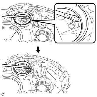
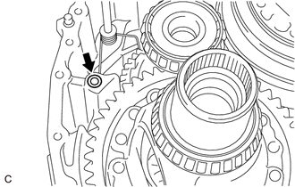
*a Protective Tape Using a screwdriver with its tip wrapped with protective tape, pry up the counter driven gear tapered roller bearing (front side outer race).
Note
Be careful not to damage the transaxle housing.
-
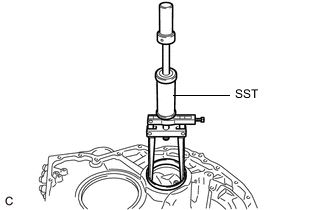
Using SST, remove the counter driven gear tapered roller bearing (front side outer race) from the transaxle housing.
- SST
- 09308-36010
-
-
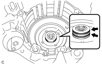
INSPECT B-1 BRAKE PISTON ROD STROKE
-
REMOVE FRONT OIL PUMP ASSEMBLY
-
Remove the 3 transaxle case gaskets from the front oil pump assembly.
-
Remove the front oil pump body O-ring from the front oil pump assembly.
-
Remove the 7 bolts and front oil pump assembly from the automatic transaxle case sub-assembly.
-
Remove the planetary carrier thrust washer from the front oil pump assembly.
-
-
REMOVE NO. 1 GOVERNOR APPLY GASKET
-
Remove the No. 1 governor apply gasket from the automatic transaxle case sub-assembly.
-
-
REMOVE MANUAL DETENT SPRING SUB-ASSEMBLY
-
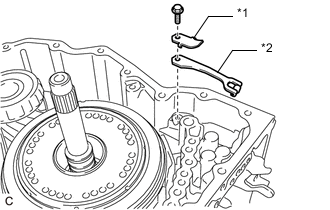
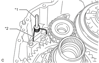
*1 Manual Detent Spring Cover *2 Manual Detent Spring Sub-assembly Remove the bolt, manual detent spring cover and manual detent spring sub-assembly from the automatic transaxle case sub-assembly.
-
-
REMOVE PARKING LOCK ROD SUB-ASSEMBLY
-
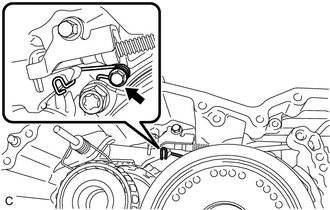
Remove the bolt, spring guide sleeve and torsion spring from the automatic transaxle case sub-assembly.
-
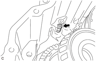
Remove the bolt and parking lock pawl bracket from the automatic transaxle case sub-assembly.
-
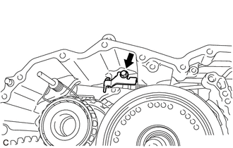
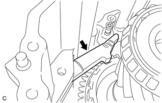
Remove the parking lock rod sub-assembly from the manual valve lever sub-assembly.
Tech Tips
Align the slot with the notches on the manual valve lever sub-assembly to remove the parking lock rod sub-assembly.
-
-
REMOVE PARKING LOCK PAWL
-
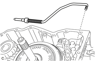
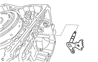
*1 Parking Lock Pawl Shaft *2 Torsion Spring Remove the parking lock pawl shaft and torsion spring from the automatic transaxle case sub-assembly.
-
Remove the parking lock pawl from the automatic transaxle case sub-assembly.
-
-
REMOVE PARKING LOCK PIN SUB-ASSEMBLY
-
Remove the parking lock pin sub-assembly from the automatic transaxle case sub-assembly.
-
-
REMOVE MANUAL VALVE LEVER SUB-ASSEMBLY
-
Remove the manual valve lever sub-assembly from the automatic transaxle case sub-assembly.
-
-
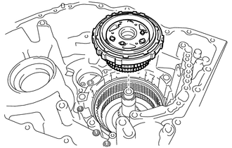
REMOVE C-3 AND C-4 CLUTCH ASSEMBLY
-
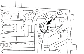
Remove the bolt from the automatic transaxle case sub-assembly.
-
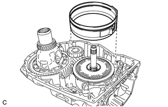
Remove the B-1 brake band assembly from the C-3 and C-4 clutch drum.
-
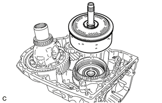
Remove the C-3 and C-4 clutch assembly with front planetary gear assembly from the automatic transaxle case sub-assembly.
-
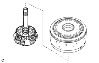
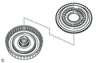
Remove the C-3 and C-4 clutch assembly from the front planetary gear assembly.
-
-
INSPECT CLEARANCE OF C-3 CLUTCH
-
INSPECT CLEARANCE OF C-4 CLUTCH
-
REMOVE NO. 3 CLUTCH DISC
-
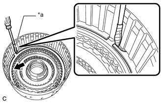
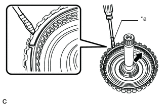
*a Protective Tape Using a screwdriver with its tip wrapped with protective tape, remove the snap ring from the C-3 and C-4 clutch sub-assembly.
Note
Be careful not to damage the C-3 and C-4 clutch sub-assembly.
-
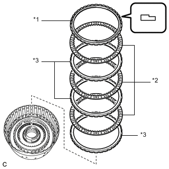
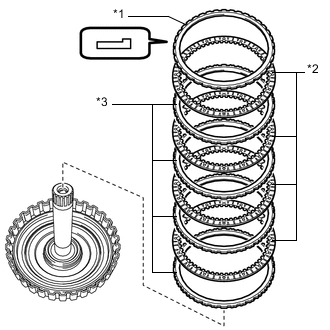
*1 Reverse Clutch Flange *2 No. 3 Clutch Disc *3 No. 3 Clutch Plate Remove the reverse clutch flange, 3 No. 3 clutch discs and 3 No. 3 clutch plates from the C-3 and C-4 clutch sub-assembly.
-
-
INSPECT NO. 3 CLUTCH DISC
-
REMOVE NO. 4 CLUTCH DISC
-
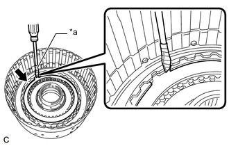
*a Protective Tape Using a screwdriver with its tip wrapped with protective tape, remove the snap ring from the C-3 and C-4 clutch sub-assembly.
Note
Be careful not to damage the C-3 and C-4 clutch sub-assembly.
-
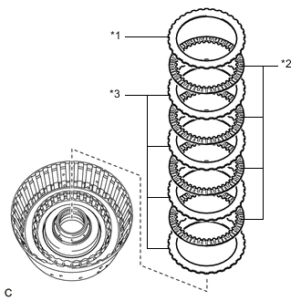
*1 No. 1 Underdrive Clutch Flange *2 No. 4 Clutch Disc *3 No. 4 Clutch Plate Remove the No. 1 underdrive clutch flange, 4 No. 4 clutch discs and 4 No. 4 clutch plates from the C-3 and C-4 clutch sub-assembly.
-
-
INSPECT NO. 4 CLUTCH DISC
-
REMOVE C-4 CLUTCH BALANCER
-
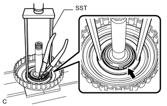
Place SST on the C-4 clutch balancer and compress the under drive return with retainer spring sub-assembly with a press.
- SST
- 09387-00020
-
Using a snap ring expander, remove the snap ring from the C-3 and C-4 clutch sub-assembly.
Note
Do not expand the snap ring excessively.
-
Remove the C-4 clutch balancer from the C-3 and C-4 clutch sub-assembly.
-
-
REMOVE UNDER DRIVE RETURN WITH RETAINER SPRING SUB-ASSEMBLY
-
Remove the under drive return with retainer spring sub-assembly from the C-3 and C-4 clutch sub-assembly.
-
-
INSPECT UNDER DRIVE RETURN WITH RETAINER SPRING SUB-ASSEMBLY
-
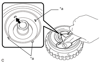
REMOVE C-4 CLUTCH PISTON
-
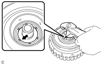
*a ATF Hole Cover the ATF holes shown in the illustration and apply compressed air (approximately 392 kPa (4.0 kgf/cm2, 57 psi)) to the ATF hole.
-
Remove the C-4 clutch piston from the C-3 and C-4 clutch sub-assembly.
-
-
REMOVE C-4 CLUTCH BALANCER O-RING
-
Remove the C-4 clutch balancer O-ring from the C-3 and C-4 clutch sub-assembly.
-
-
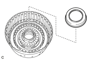
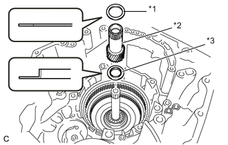
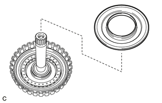
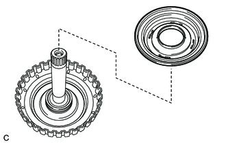
REMOVE FRONT PLANETARY GEAR ASSEMBLY
-
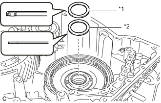
*1 No. 2 Planetary Carrier Thrust Washer *2 No. 7 Thrust Bearing Race Remove the No. 2 planetary carrier thrust washer and No. 7 thrust bearing race from the front planetary gear assembly.
-
Remove the planetary sun gear from the front planetary gear assembly.
-
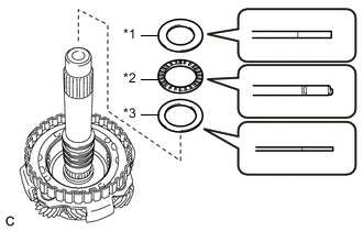
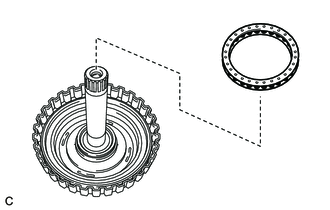
*1 No. 9 Thrust Bearing Race *2 Thrust Needle Roller Bearing *3 No. 8 Thrust Bearing Race Remove the No. 9 thrust bearing race, thrust needle roller bearing and No. 8 thrust bearing race from the front planetary gear assembly.
-
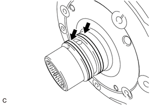
Remove the 2 rear input shaft oil seal rings from the front planetary gear assembly.
-
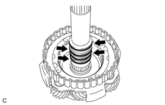
Remove the 4 input shaft oil seal rings from the front planetary gear assembly.
-
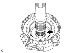
Remove the needle roller bearing from the front planetary gear assembly.
-
-
INSPECT FRONT PLANETARY GEAR ASSEMBLY
-
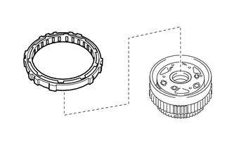
REMOVE FRONT PLANETARY RING GEAR
-
Remove the thrust needle roller bearing from the front planetary ring gear flange.
-
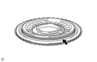
Remove the front planetary ring gear with front planetary ring gear flange from the C-1 clutch assembly.
-
*a Protective Tape Using a screwdriver with its tip wrapped with protective tape, remove the snap ring from the front planetary ring gear.
Note
Be careful not to damage the front planetary ring gear.
-
Remove the front planetary ring gear flange from the front planetary ring gear.
-
-
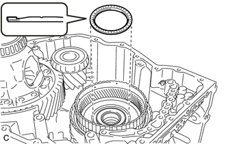
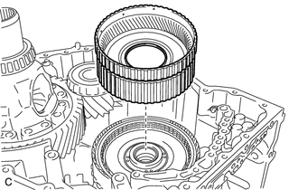
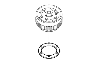
REMOVE C-1 CLUTCH ASSEMBLY
-
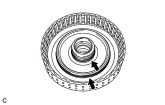
*1 Thrust Needle Roller Bearing *2 No. 6 Thrust Bearing Race Remove the thrust needle roller bearing and No. 6 thrust bearing race from the C-1 clutch assembly.
-
Remove the C-1 clutch assembly from the rear planetary sun gear sub-assembly.
-
-
INSPECT CLEARANCE OF C-1 CLUTCH
-
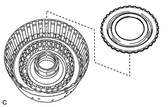
REMOVE FORWARD MULTIPLE DISC CLUTCH DISC
-
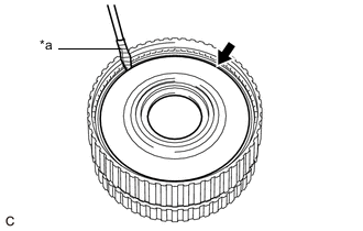
*a Protective Tape Using a screwdriver with its tip wrapped with protective tape, remove the snap ring from the clutch drum sub-assembly.
Note
Be careful not to damage the clutch drum sub-assembly.
-
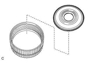
*1 Forward Clutch Flange *2 Forward Multiple Disc Clutch Disc *3 Forward Multiple Disc Clutch Plate Remove the forward clutch flange, 5 forward multiple disc clutch discs and 5 forward multiple disc clutch plates from the clutch drum sub-assembly.
-
-
INSPECT FORWARD MULTIPLE DISC CLUTCH DISC
-
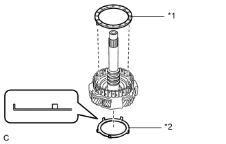
REMOVE NO. 1 CLUTCH BALANCER
-
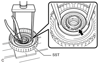
Place SST on the No. 1 clutch balancer and compress the forward clutch return spring sub-assembly with a press.
- SST
- 09387-00020
-
Using a snap ring expander, remove the snap ring from the clutch drum sub-assembly.
Note
Do not expand the snap ring excessively.
-
Remove the No. 1 clutch balancer from the clutch drum sub-assembly.
-
-
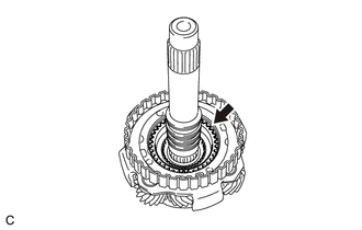
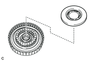
REMOVE FORWARD CLUTCH RETURN SPRING SUB-ASSEMBLY
-
Remove the forward clutch return spring sub-assembly from the clutch drum sub-assembly.
-
-
INSPECT FORWARD CLUTCH RETURN SPRING SUB-ASSEMBLY
-
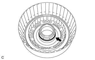
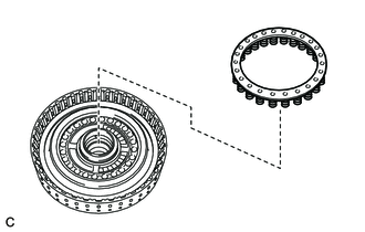
REMOVE FORWARD CLUTCH PISTON
-
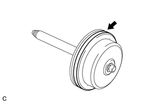
*a ATF Hole Cover the ATF hole shown in the illustration and apply compressed air (approximately 392 kPa (4.0 kgf/cm2, 57 psi)) to the ATF hole.
-
Remove the forward clutch piston from the clutch drum sub-assembly.
-
Remove the O-ring from the forward clutch piston.
-
-
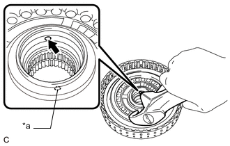
REMOVE C-1 DRUM O-RING
-
Remove the 2 C-1 drum O-rings from the clutch drum sub-assembly.
-
-
REMOVE INPUT SUN GEAR DRUM
-

*1 Thrust Needle Roller Bearing *2 No. 5 Thrust Bearing Race Remove the thrust needle roller bearing and No. 5 thrust bearing race from the input sun gear drum.
-
Remove the input sun gear drum from the rear planetary gear assembly.
-
-
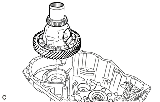
REMOVE PINION AND COUNTER DRIVEN GEAR SUB-ASSEMBLY
-
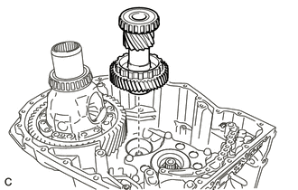
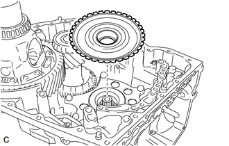
Remove the pinion and counter driven gear sub-assembly from the automatic transaxle case sub-assembly.
-
-
REMOVE COUNTER DRIVEN GEAR TAPERED ROLLER BEARING (FRONT SIDE INNER RACE)
-
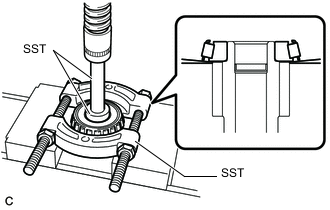
Using SST and a press, remove the counter driven gear tapered roller bearing (front side inner race) from the pinion and counter driven gear sub-assembly.
- SST
- 09950-00020
- 09950-60010 ( 09951-00400 )
- 09950-70010 ( 09951-07100 )
-
-
REMOVE COUNTER DRIVEN GEAR TAPERED ROLLER BEARING (REAR SIDE INNER RACE)
-
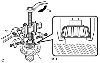
*a Turn *b Hold Using SST, remove the counter driven gear tapered roller bearing (rear side inner race) from the pinion and counter driven gear sub-assembly.
- SST
- 09950-40011 ( 09951-04010, 09952-04010, 09953-04030, 09954-04010, 09955-04061, 09957-04010, 09958-04011 )
- 09950-60010 ( 09951-00320 )
-
-
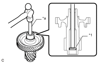
REMOVE TIGHT PLUG (COUNTER DRIVEN GEAR SIDE)
-
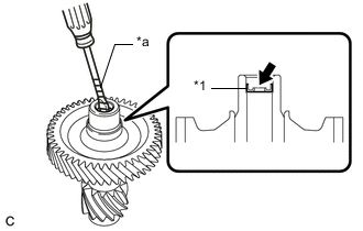
*1 Tight Plug (Counter Driven Gear Side) *a Protective Tape Using a screwdriver with its tip wrapped with protective tape, remove the tight plug (counter driven gear side) from the pinion and counter driven gear sub-assembly.
Note
Be careful not to damage the pinion and counter driven gear sub-assembly.
-
-
REMOVE TIGHT PLUG (DIFFERENTIAL DRIVEN PINION SIDE)
-
*1 Tight Plug (Differential Drive Pinion Side) *a Brass Bar Using a brass bar and a hammer, remove the tight plug (differential drive pinion side) from the pinion and counter driven gear sub-assembly.
Note
Be careful not to damage the pinion and counter driven gear sub-assembly.
-
-
REMOVE DIFFERENTIAL CASE ASSEMBLY
-
Remove the differential case assembly from the automatic transaxle case sub-assembly.
-
-
REMOVE DIFFERENTIAL CASE TAPERED ROLLER BEARING (REAR SIDE OUTER RACE)
-
Using SST, remove the differential case tapered roller bearing (rear side outer race) and shim from the automatic transaxle case sub-assembly.
- SST
- 09308-00010
-
-
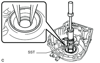
REMOVE FRONT DRIVE SHAFT OIL SEAL LH
-
Using SST and a hammer, remove the front drive shaft oil seal LH from the automatic transaxle case sub-assembly.
- SST
- 09950-60010 ( 09951-00650 )
- 09950-70010 ( 09951-07200 )
-
-
REMOVE COUNTER DRIVEN GEAR TAPERED ROLLER BEARING (REAR SIDE OUTER RACE)
-
Using SST, remove the counter driven gear tapered roller bearing (rear side outer race) and shim from the automatic transaxle case sub-assembly.
- SST
- 09308-00010
-
-
REMOVE TRANSMISSION LUBE APPLY TUBE
-
Remove the bolt and clamp from the automatic transaxle case sub-assembly.
-
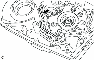
Remove the transmission lube apply tube from the automatic transaxle case sub-assembly.
-
-
REMOVE B-1 BRAKE PISTON
-
Using snap ring pliers, remove the snap ring from the automatic transaxle case sub-assembly.
-
Set the automatic transaxle case sub-assembly so that the B-1 brake piston is positioned downward.
-
Apply compressed air (approximately 392 kPa (4.0 kgf/cm2, 57 psi)) to the ATF hole.
Note
-
Make sure that the B-1 brake piston is positioned downward. Applying compressed air will remove the B-1 brake piston.
-
Use a piece of cloth to keep the B-1 brake piston from flying out.
-
-
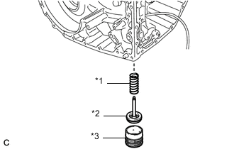
*1 B-1 Brake Piston Compression Spring *2 B-1 Brake Piston *3 Brake Piston Cover Remove the brake piston cover, B-1 brake piston and B-1 brake piston compression spring from the automatic transaxle case sub-assembly.
-
Remove the 3 O-rings from the brake piston cover.
-
Remove the O-ring from the B-1 brake piston.
-
-
REMOVE FRONT PLANETARY GEAR SUB-ASSEMBLY
-
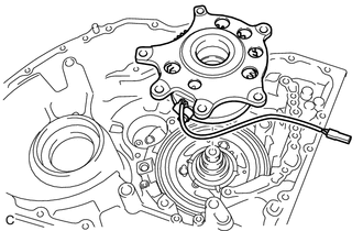
Disengage the wire harness clamp.
-
Remove the bolt and clamp from the automatic transaxle case sub-assembly.
-
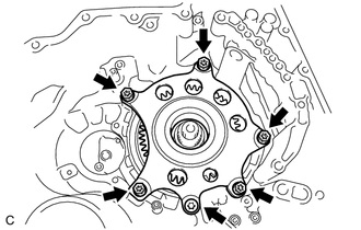
Using a T55 "TORX" socket wrench, remove the 6 bolts.
-
Remove the front planetary gear sub-assembly from the automatic transaxle case sub-assembly.
-
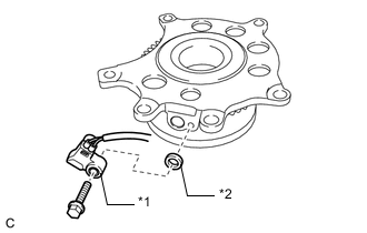
*1 Transmission Revolution Sensor (NC) *2 Spacer Remove the bolt, transmission revolution sensor (NC) and spacer from the front planetary gear sub-assembly.
-
-
REMOVE PLANETARY SUN GEAR SUB-ASSEMBLY
-
Remove the planetary sun gear sub-assembly from the rear planetary gear assembly.
-
Remove the thrust needle roller bearing from the rear planetary gear assembly.
-
-
REMOVE REAR PLANETARY GEAR ASSEMBLY
-
Remove the No. 3 planetary carrier thrust washer from the rear planetary gear assembly.
-
*a Protective Tape Using a screwdriver with its tip wrapped with protective tape, remove the snap ring from the automatic transaxle case sub-assembly.
Note
Be careful not to damage the automatic transaxle case sub-assembly.
-
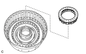
Remove the one-way clutch assembly with rear planetary gear assembly from the C-2 clutch assembly.
-
Remove the one-way clutch assembly from the rear planetary gear assembly.
-
Remove the No. 4 planetary carrier thrust washer from the rear planetary gear assembly.
-
-
INSPECT ONE-WAY CLUTCH ASSEMBLY
-
INSPECT REAR PLANETARY GEAR ASSEMBLY
-
REMOVE REAR PLANETARY SUN GEAR SUB-ASSEMBLY
-
*1 No. 4 Thrust Bearing Race *2 Rear Planetary Sun Gear Sub-assembly *3 No. 3 Thrust Bearing Race Remove the rear planetary sun gear sub-assembly from the C-2 clutch assembly.
-
Remove the No. 4 thrust bearing race and No. 3 thrust bearing race from the rear planetary sun gear sub-assembly.
-
-
INSPECT REAR PLANETARY SUN GEAR SUB-ASSEMBLY
-
INSPECT CLEARANCE OF NO. 2 BRAKE
-
INSPECT CLEARANCE OF C-2 CLUTCH
-
REMOVE 1ST AND REVERSE BRAKE CLUTCH DISC
-
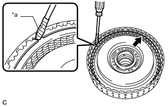
*a Protective Tape Using a screwdriver with its tip wrapped with protective tape, remove the snap ring from the automatic transaxle case sub-assembly.
Note
Be careful not to damage the automatic transaxle case sub-assembly.
-
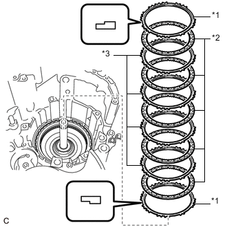
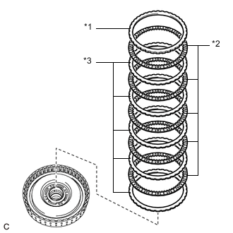
*1 1st and Reverse Brake Flange *2 1st and Reverse Brake Clutch Disc *3 1st and Reverse Brake Clutch Plate Remove the 2 1st and reverse brake flanges, 5 1st and reverse brake clutch discs and 4 1st and reverse brake clutch plates from the automatic transaxle case sub-assembly.
-
-
INSPECT 1ST AND REVERSE BRAKE CLUTCH DISC
-
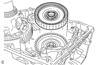
REMOVE C-2 CLUTCH ASSEMBLY
-
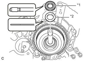
*1 Thrust Needle Roller Bearing *2 No. 2 Thrust Bearing Race Remove the thrust needle roller bearing and No. 2 thrust bearing race from the C-2 clutch assembly.
-
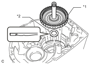
*1 C-2 Clutch Assembly *2 Thrust Needle Roller Bearing Remove the C-2 clutch assembly from the automatic transaxle case sub-assembly.
-
Remove the thrust needle roller bearing from the C-2 clutch assembly.
-
-
REMOVE NO. 2 CLUTCH DISC
-
*a Protective Tape Using a screwdriver with its tip wrapped with protective tape, remove the snap ring from the intermediate shaft sub-assembly.
Note
Be careful not to damage the intermediate shaft sub-assembly.
-
*1 Direct Clutch Flange *2 No. 2 Clutch Disc *3 No. 2 Clutch Plate Remove the direct clutch flange, 4 No. 2 clutch discs and 4 No. 2 clutch plates from the intermediate shaft sub-assembly.
-
-
INSPECT NO. 2 CLUTCH DISC
-
REMOVE C-2 CLUTCH BALANCER
-
Place SST on the C-2 clutch balancer and compress the clutch return with retainer spring sub-assembly with a press.
- SST
- 09387-00020
-
Using a snap ring expander, remove the snap ring from the intermediate shaft sub-assembly.
Note
Do not expand the snap ring excessively.
-
Apply compressed air (approximately 392 kPa (4.0 kgf/cm2, 57 psi)) to the ATF hole.
-
Remove the C-2 clutch balancer from the intermediate shaft sub-assembly.
-
-
REMOVE CLUTCH RETURN WITH RETAINER SPRING SUB-ASSEMBLY
-
Remove the clutch return with retainer spring sub-assembly from the intermediate shaft sub-assembly.
-
-
INSPECT CLUTCH RETURN WITH RETAINER SPRING SUB-ASSEMBLY
-
REMOVE C-2 CLUTCH PISTON
-
*a ATF Hole Cover the ATF holes shown in the illustration and apply compressed air (approximately 392 kPa (4.0 kgf/cm2, 57 psi)) to the ATF hole.
-
Remove the C-2 clutch piston from the intermediate shaft sub-assembly.
-
-
REMOVE INTERMEDIATE SHAFT O-RING
-
Remove the 2 intermediate shaft O-rings from the intermediate shaft sub-assembly.
-
-
REMOVE 1ST AND REVERSE BRAKE PISTON
-
*a Protective Tape Place SST on the 1st and reverse brake return spring sub-assembly and compress it with a press.
- SST
- 09387-00140
- 09950-60010 ( 09951-00650 )
- 09950-70010 ( 09951-07200 )
Note
-
Place SST on the 1st and reverse brake return spring sub-assembly as shown in the illustration.
-
Make sure that SST does not interfere with the 1st and reverse brake piston.
-
Using a screwdriver with its tip wrapped with protective tape, remove the snap ring from the automatic transaxle case sub-assembly.
Note
Be careful not to damage the automatic transaxle case sub-assembly.
-
Remove the 1st and reverse brake return spring sub-assembly from the 1st and reverse brake piston.
-
Apply compressed air (approximately 392 kPa (4.0 kgf/cm2, 57 psi)) to the ATF hole to remove the 1st and reverse brake piston from the automatic transaxle case sub-assembly.
-
Remove the 2 O-rings from the 1st and reverse brake piston.
-
-
INSPECT 1ST AND REVERSE BRAKE RETURN SPRING SUB-ASSEMBLY
-
REMOVE NO. 1 THRUST BEARING RACE
-
Remove the No. 1 thrust bearing race from the automatic transaxle case sub-assembly.
-
-
REMOVE DIRECT CLUTCH DRUM OIL SEAL RING
-
Remove the 2 direct clutch drum oil seal rings from the automatic transaxle case sub-assembly.
-
-
REMOVE BREATHER PLUG
-
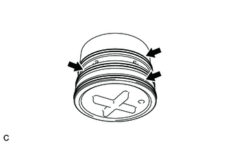
*a Push out Disengage each claw and remove the breather plug from the automatic transaxle case sub-assembly.
-
Using a screwdriver with its tip wrapped with protective tape, remove the O-ring from the breather plug.
Note
Be careful not to damage the breather plug.
-
-
REMOVE MANUAL VALVE LEVER SHAFT OIL SEAL
-
*a Protective Tape Using a screwdriver with its tip wrapped with protective tape, remove the manual valve lever shaft oil seal from the automatic transaxle case sub-assembly.
Note
Be careful not to damage the automatic transaxle case sub-assembly.
-
-
REMOVE NO. 1 TRANSAXLE CASE PLUG
-
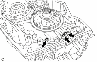
Remove the 4 No. 1 transaxle case plugs from the automatic transaxle case sub-assembly.
-
Remove the 4 O-rings from the 4 No. 1 transaxle case plugs.
-
Remove the 3 No. 1 transaxle case plugs from the transaxle housing.
-
Remove the 3 O-rings from the 3 No. 1 transaxle case plugs.
-
-
REMOVE NO. 2 TRANSAXLE CASE PLUG
-
Using a T55 "TORX" socket wrench, remove the 2 No. 2 transaxle case plugs from the transaxle housing.
-
Remove the 2 O-rings from the 2 No. 2 transaxle case plugs.
-
Using a T55 "TORX" socket wrench, remove the 2 No. 2 transaxle case plugs from the automatic transaxle case sub-assembly.
-
Remove the 2 O-rings from the 2 No. 2 transaxle case plugs.
-