POWER BACK DOOR SYSTEM SYSTEM DESCRIPTION
-
POWER BACK DOOR SYSTEM DESCRIPTION
-
The power back door system controls the power back door by automatically opening and closing the power back door with a motor.
-
The power back door system operates only when the necessary conditions are met.
-
The multiplex network door ECU records the position of the power back door in the multiplex network door ECU.
If the cable is disconnected from the negative (-) battery terminal or the fuses in the power source circuit of the power back door system or multiplex network door ECU is removed and reinstalled, the position of the power back door recorded in the multiplex network door ECU will be cleared.
In this case, initialization of the multiplex network door ECU is necessary. Refer to Initialization.
-
The multiplex network door ECU receives open/close request signals for the back door. The multiplex network door ECU controls the power back door opening/closing operations by sending commands to the back door lock assembly and back door motor.
-
The power back door system has various request signals: open/close request signals from the transmitter switch (electrical key transmitter sub-assembly), open/close request signals from the combination switch assembly, open request signal from the back door opener switch assembly, open/close request signals from the back door control switch and on/off request signals from the combination meter assembly.
-
The power back door system sounds a buzzer and flashes the hazard warning lights* when the power back door starts operating.
-
*: w/ Power Back Door Hazard Warning Light
-
-
The power back door system will not reverse the direction that the power back door is operating if any switch is pressed while it is operating.
-
The power back door system will stop the operation of the power back door if any switch is pressed while it is operating.
-
A pulse sensor and power back door sensor assemblies are used to prevent anything from being caught in the door while the power back door is closing (jam protection function).
-
-
Function of main components:
Component Function Power back door warning buzzer
-
Sounds for 0.8 seconds when the combination switch assembly, back door control switch, back door opener switch assembly or transmitter switch (electrical key transmitter sub-assembly) is pressed.
-
Sounds twice for 0.1 seconds to notify that the power back door has stopped operating when the jam protection function is activated.
-
Sounds for 0.2 seconds when the back door opener switch assembly is pressed while the power back door is operating.
Hazard warning lights (w/ Power Back Door Hazard Warning Light) Flash twice when an open/close request signal is input from a switch while the back door is in the closed or fully open position to notify that the power back door will start operating. Combination meter assembly
-
Disables the power back door system when the power back door function is set to OFF.
-
Enables the power back door system when the power back door function is set to ON.
Transmitter switch (electrical key transmitter sub-assembly)
-
Causes the power back door to open/close when pressed
-
Stops the power back door when pressed during an operation.
Back door control switch Transmits a power back door open/close request signal to the multiplex network door ECU via the main body ECU (multiplex network body ECU). Back door opener switch assembly Transmits a power back door open request signal to the multiplex network door ECU via the certification ECU (smart key ECU assembly). Power back door switch (integration control and panel assembly) Transmits a power back door open/close request signal to the multiplex network door ECU via the main body ECU (multiplex network body ECU). Rear emblem sensor assembly Transmits a power back door open request signal to the multiplex network door ECU. -
-
-
POWER BACK DOOR OPERATION TIMING CHART
-
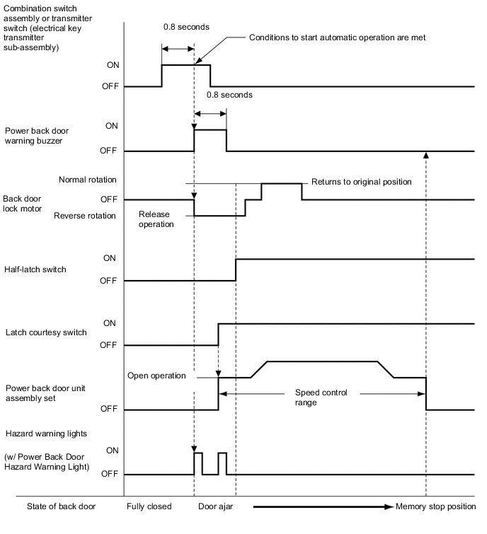
Opening Operation (using combination switch assembly or transmitter switch (electrical key transmitter sub-assembly)):
-
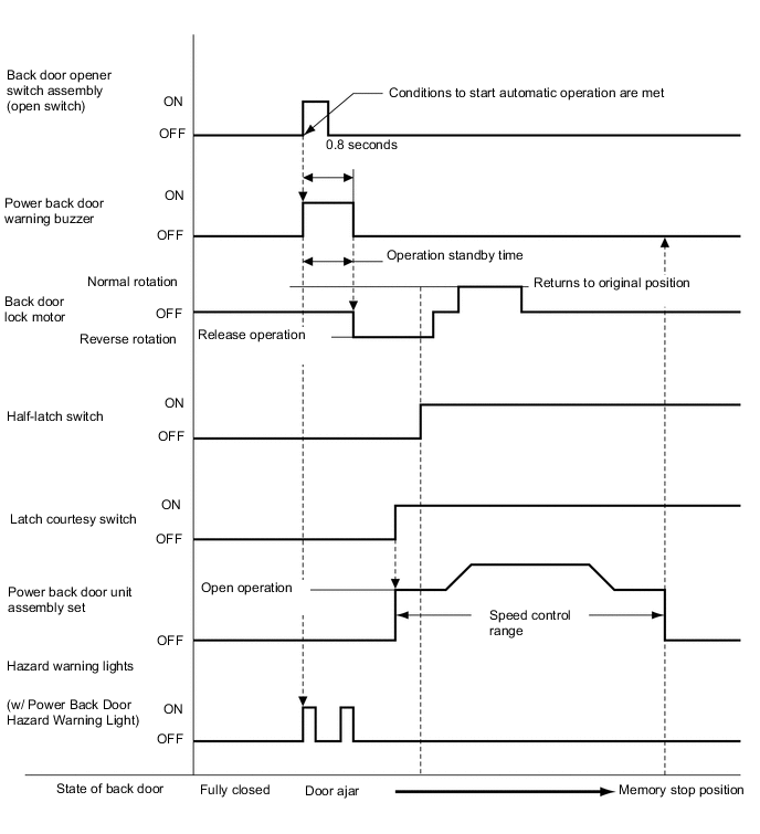
Opening Operation (using back door opener switch assembly):
-
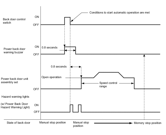
Opening operation (using back door control switch):
-
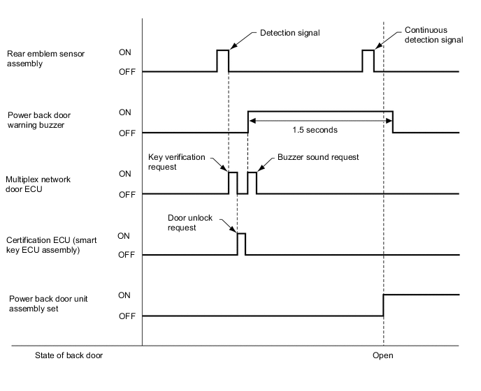
Opening operation (using rear emblem sensor assembly):
-
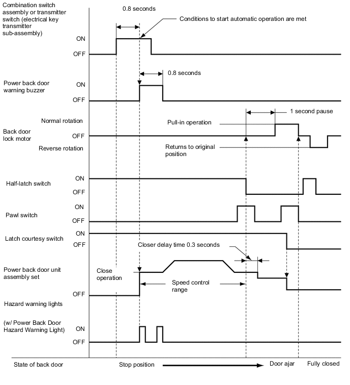
Closing Operation (using combination switch assembly or transmitter switch (electrical key transmitter sub-assembly)):
-
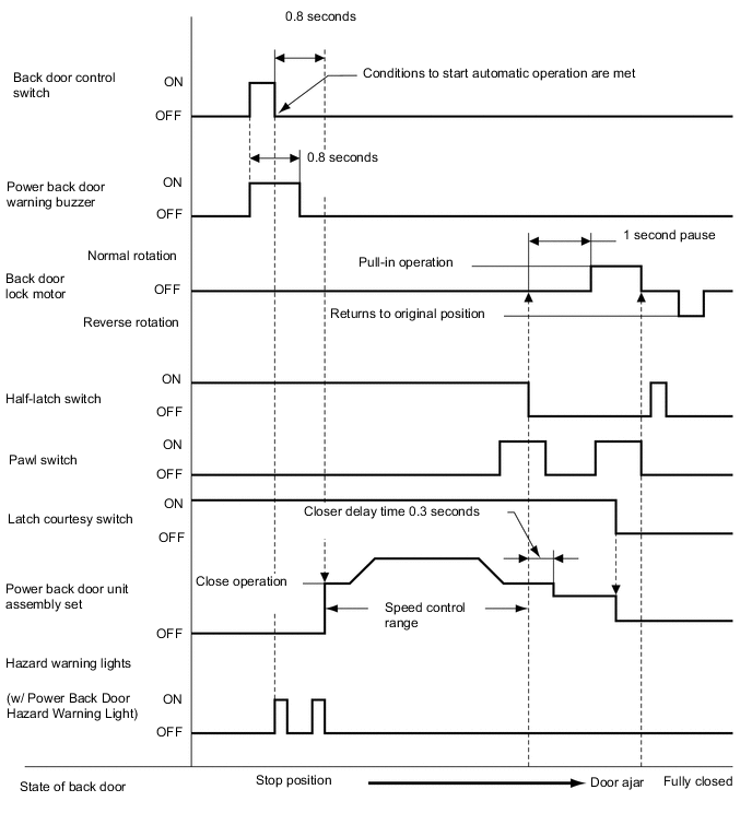
Closing Operation (using back door control switch):
-