ECD SYSTEM (w/o EGR Cooler) DATA LIST / ACTIVE TEST
-
READ DATA LIST
Tech Tips
Using the intelligent tester's Data List allows switch, sensor, actuator, and other item values to be read without removing any parts. Reading the Data List early in troubleshooting is one way to save time.
Note
In the table below, the values listed under "Normal Condition" are reference values. Do not depend solely on these reference values when deciding whether a part is faulty or not.
-
Warm up the engine.
-
Turn the ignition switch OFF.
-
Connect the intelligent tester to the DLC3.
-
Turn the ignition switch ON.
-
Turn the intelligent tester ON.
-
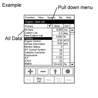
Enter the following menus: Powertrain / Engine and ECT / Data List.
Tech Tips
To display the entire Data List, press the pull down menu button next to Primary. Then select All Data.
-
Read the Data List.
Tester Display Measurement Item/Range Normal Condition Diagnostic Note Vehicle Speed Vehicle speed:
Min.: 0 km/h, Max.: 255 km/h
Actual vehicle speed Speed indicated on speedometer Engine Speed Engine speed:
Min.: 0 rpm, Max.: 16,383 rpm
700 to 800 rpm: Idling after engine warmed up - Calculate Load Calculated load by ECM:
Min.: 0%, Max.: 100%
-
10 to 40%: Idling after engine warmed up
-
10 to 40%: Running without load (2500 rpm)
- MAF Air flow rate from MAF meter status:
Min.: 0 gm/s, Max.: 655.35 gm/s
-
6 to 15 gm/s: Idling after engine warmed up
-
25 to 35 gm/s: Running without load (2000 rpm)
If value approximately 0 gm/s:
-
Mass air flow meter power source circuit open
-
VG circuit open or shorted
If value 180 gm/s or more:
-
EVG circuit open
Atmosphere Pressure Atmospheric pressure value:
Min.: 0 kPa,
Max.: 255 kPa
Actual atmospheric pressure - MAP Absolute pressure inside intake manifold:
Min.: 0 kPa, Max.: 255 kPa
-
95 to 105 kPa: Idling after engine warmed up
-
100 to 120 kPa: Running without load (2000 rpm)
-
110 to 140 kPa: Running without load (3000 rpm)
- Coolant Temp Engine coolant temperature:
Min.: -40°C, Max.: 140°C
80 to 95°C (176 to 203°F):
After warming up engine
If value is -40°C (-40°F) or 140°C (284°F), sensor circuit open or shorted Intake Air Intake air temperature:
Min.: -40°C, Max.: 140°C
Equivalent to temperature at location of mass air flow meter If value is -40°C (-40°F) or 140°C (284°F), sensor circuit open or shorted Engine Run Time Engine run time:
Min.: 0 s,
Max.: 65,535 s
Time after engine started Service data Initial Engine Coolant Temp Initial engine coolant temperature:
Min.: -40°C, Max.: 120°C
ECT when engine starts - Initial Intake Air Temp Initial intake air temperature:
Min.: -40°C, Max.: 120°C
Intake air temperature when engine starts - Battery Voltage Battery voltage:
Min.: 0 V,
Max.: 65.5 V
9 to 14 V: Idling - Alternate Duty Ratio Alternate duty ratio:
Min.: 0%, Max.: 100%
-
No electrical load:
20 to 60%
-
High electrical load:
100%
- Pre Glow Pre-glow operation:
ON or OFF
- This is the ECM command. After Glow After-glow operation:
ON or OFF
- This is the ECM command. Accel Position Accelerator position status:
Min.: 0%, Max.: 99.60%
-
Accelerator pedal released:
0%
-
Accelerator pedal depressed:
99.60%
Read value with ignition switch ON (do not start engine) Accel Sens. No.1 Volt % Accelerator position No. 1:
Min.: 0%, Max.: 100%
-
Accelerator pedal released:
10 to 22%
-
Accelerator pedal fully depressed:
52 to 90%
Read value with ignition switch ON (do not start engine) Accel Sens. No.2 Volt % Accelerator position No. 2:
Min.: 0%, Max.: 100%
-
Accelerator pedal released:
24 to 40%
-
Accelerator pedal fully depressed:
68 to 99%
Read value with ignition switch ON (do not start engine) Target Throttle Position Target throttle position
Min.: -128%, Max.: 127%
-
Throttle valve fully opened:
0%
-
Throttle valve fully closed:
100%
If there is a malfunction of the throttle actuator, compare the target and actual throttle position values for troubleshooting. Actual Throttle Position Actual diesel throttle position:
Min.: -128%, Max.: 127%
- - Throttle Close Learning Val. Throttle fully closed position learned value:
Min.: 0 deg, Max.: 84 deg
- - Diesel Throttle Learn Status Diesel throttle learn status:
OK or NG
OK - Injection Volume Injection volume:
Min.: 0 mm3/st, Max.: 1,279.98 mm3/st
3 to 10 mm3/st: Idling
- Inj. FB Vol. for Idle Idle stability status integral control volume:
Min.: -80 mm3/st, Max.: 79.99 mm3/st
-10 to 10 mm3/st
- Inj Vol Feedback Learning Injection volume compensation learned value:
Min.: -10 mm3/st, Max.: 9.9 mm3/st
-4.0 to 4.0 mm3/st: Idling
- Injection Feedback Val #1 Injection volume correction for cylinder 1:
Min.: -10 mm3/st, Max.: 10 mm3/st
-3.0 to 3.0 mm3/st: Idling
-
"Injection Feedback Val" more than 3.0 mm3/st: Injector breakdown is causing injection volume deviation, or insufficient compression is causing poor combustion.
-
Even if "Injection Feedback Val" for a cylinder is less than -3.0 mm3/st, the cylinder with this value does not necessarily have a problem.
Tech Tips
-
The ECM adjusts each cylinder so that the average "Injection Feedback Val" of the 4 cylinders is approximately 0 mm3/st.
-
If more than one cylinder has a positive correction value, a normal cylinder may have a value less than -3.0 mm3/st.
-
Injection Feedback Val #2 Injection volume correction for cylinder 2:
Min.: -10 mm3/st, Max.: 10 mm3/st
-3.0 to 3.0 mm3/st: Idling
Injection Feedback Val #3 Injection volume correction for cylinder 3:
Min.: -10 mm3/st, Max.: 10 mm3/st
-3.0 to 3.0 mm3/st: Idling
Injection Feedback Val #4 Injection volume correction for cylinder 4:
Min.: -10 mm3/st, Max.: 10 mm3/st
-3.0 to 3.0 mm3/st: Idling
Pilot 1 Injection Period Pilot 1 injection period:
Min.: 0 μs, Max.: 65,535 μs
- - Pilot 2 Injection Period Pilot 2 injection period:
Min.: 0 μs, Max.: 65,535 μs
310 to 410 μs: Idling - Main Injection Period Main injection period:
Min.: 0 μs, Max.: 65,535 μs
450 to 640 μs: Idling - After Injection Period After injection period:
Min.: 0 μs, Max.: 65,535 μs
- - Pilot 1 Injection Timing Pilot 1 injection timing:
Min.: -70°CA, Max.: 20°CA
- - Pilot 2 Injection Timing Pilot 2 injection timing:
Min.: -50°CA, Max.: 20°CA
-10.8 to -9.8°CA: idle after engine warmed up and vehicle is under normal atmospheric pressure - Main Injection Timing Main injection timing:
Min.: -90°CA, Max.: 90°CA
2.0 to 3.0°CA: idle after engine warmed up and vehicle is under normal atmospheric pressure - After Injection Timing After injection timing:
Min.: -10°CA, Max.: 50°CA
- - Injector Memory Error Injector Memory Error:
No Error or Error
No Error If the fuel injector compensation codes are not input into the new ECM, or if a fuel injector compensation code of a different injector model or a compensation code representing a value which exceeds the compensation setting range is input into the new ECM, DTC P1601 is stored and "Injector Memory Error" displays "Error". Reju Pilot Quantity Learning Pilot quantity learning prohibition state:
READY or NG
- - Pilot Quantity Learning State of "Pilot Quantity Learning":
Standby / Wait / Learn / Stop / Comple
- If "Pilot Quantity Learning" is incomplete, the MIL illuminates and DTC P1601 is stored. Injection Pressure Correction Injection pressure correction:
Min.: -500 mm3/st,
Max.: 779.9 mm3/st
-400 to 400 mm3/st
- Target Common Rail Pressure Target common rail pressure:
Min.: 0 kPa, Max.: 655350 kPa
20000 to 180000 kPa - Fuel Press Fuel pressure:
Min.: 0 kPa, Max.: 655350 kPa
25000 to 35000 kPa: Idling - Common Rail Pres Sens 2 Common rail pressure sensor (Sub)
Min.: 0 kPa, Max.: 655350 kPa
25000 to 35000 kPa: Idling - Fuel Temperature Fuel temperature:
Min.: -40°C, Max.: 215°C
Actual fuel temperature ECD freeze frame data Fuel Return Temp Fuel return temperature:
Min.: -40°C, Max.: 215°C
Idling after engine warmed-up: 35 to 85°C If the "Fuel Return Temp" value is not between 35°C (95°F) and 110°C (230°F), "Pilot Quantity Learning" is prohibited. Target Pump SCV Current Pump current target final value:
Min.: 0 mA, Max.: 4000 mA
- - Pressure Discharge Valve Pressure discharge valve operation:
ON or OFF
ON: Pressure discharge valve open This is the ECM command. Target EGR Position EGR valve target opening angle:
Min.: 0%, Max.: 100%
Level surface, engine warmed up and engine idling:
50 to 100%
- Actual EGR Valve Pos. EGR valve position:
Min.: 0%, Max.: 100%
Idling after engine warmed up:
60 to 80%
- EGR Lift Sensor Volt % EGR lift position:
Min.: 0%, Max.: 99.6%
- - EGR Close Lrn. Val. EGR fully closed position learned value:
Min.: 0 V, Max.: 5 V
Level surface, room temperature, engine warmed up and engine idling:
0 to 1 V
- EGR Close Lrn. Status EGR valve fully closed position learning status:
OK or NG
OK - EGR Operation Prohibit EGR operation prohibition:
OK or NG
OK: Possible to perform "Control the EGR Step Position" Active Test
-
OK: "EGR Valve Control Active Test Possible" Condition.
-
NG: "Not Possible" Condition.
VN Turbo Type VN turbo type:
Not. Avl or Commo or Vacuum
Not. Avl - Starter Signal Starter signal:
ON or OFF
ON: Cranking - Clutch Switch Clutch switch:
ON or OFF
ON: Clutch pedal depressed - Stop Light Switch Stop light switch:
ON or OFF
-
ON: Brake pedal depressed
-
OFF: Brake pedal released
- A/C Signal A/C signal:
ON or OFF
ON: A/C ON - Immobiliser Communication Immobiliser communication:
ON or OFF
-
ON: Normal
-
OFF: Engine cannot be started due to immobiliser communication malfunction
- Check Mode Check mode:
ON or OFF
ON: Check mode ON - SPD Test Result Check mode result for vehicle speed sensor:
Compl or Incompl
- - # Codes(Include History) Number of codes:
Min.: 0, Max.: 255
- Number of detected DTCs MIL MIL status:
ON or OFF
ON: MIL ON - Time After DTC Cleared Time after DTC cleared:
Min.: 0 minutes,
Max.: 65,535 min
Equivalent to time after DTCs were erased - Distance from DTC Cleared Distance after DTC cleared:
Min.: 0 km,
Max.: 65,535 km
Equivalent to drive distance after DTCs were erased - Warmup Cycle Cleared DTC Warmup cycle after DTC cleared:
Min.: 0,
Max.: 255
- Number of warmup cycles after DTC cleared OBD Requirements Identifying OBD requirement - - Number of Emission DTC Number of emission DTCs - - TC and TE1 TC and TE1 terminal of DLC3:
ON or OFF
- Active Test support data Engine Start Time Engine start time:
Min.: 0 ms,
Max.: 267000 ms
- Time necessary for the engine to start. Engine Speed (Starter Off) Engine speed when starter off:
Min.: 0 rpm,
Max.: 1593 rpm
- Engine speed immediately after starting the engine. Starter Count Starter on count:
Min.: 0,
Max.: 255
- Number of times the starter turned on from the time the ignition switch was turned to ON. Run Dist of Previous Trip Distance driven during previous trip:
Min.: 0 km,
Max.: 326 km
- Used to confirm the driving conditions of the previous trip (before the malfunction occurred). Electric Duty Feedback Value Electric load feedback value:
Min.: 0 mm3/st,
Max.: 39.8 mm3/st
0 to 10 mm3/st
Expected injection volume increase after the electrical load turns from off to on. A/C Duty Feedback Value A/C load feedback value:
Min.: 0 mm3/st,
Max.: 39.8 mm3/st
0 to 10 mm3/st
Expected injection volume increase after the A/C turns from off to on. PS Duty Feedback Value Power steering load feedback value:
Min.: 0 mm3/st,
Max.: 39.8 mm3/st
0 to 10 mm3/st
Expected injection volume increase after the power steering turns from off to on. Idle Injection Volume (Min) Injection volume feedback learned value:
Min.: 0 mm3/st,
Max.: 39.8 mm3/st
0 to 5 mm3/st
-
When the engine is warmed up and in a stable idling condition, this learning will be performed.
-
Only when the ignition switch is turned off is the learned value updated gradually.
ACT VSV A/C cut status for Active Test:
ON or OFF
- Active Test support data Model Code Model code - Identifying model code: Engine Type Engine type - Identifying engine type:
2KDFTV
Cylinder Number Cylinder number:
Min.: 0, Max.: 255
- Identifying cylinder number:
4
Transmission Type Transmission type - Identifying transmission type:
MT
Destination Destination - Identifying destination:
V
Model Year Model year:
Min.: 1900, Max.: 2155
- Identifying mode year:
20##
System Identification System Identification - - Engine Speed of Cyl #1 Engine speed for No. 1 cylinder:
Min.: 0 rpm, Max.: 51199 rpm
"Engine speed" of all cylinders almost same
-
Output only when the Active Test "Check the Cylinder Compression" is performed.
-
Indicates the speed of each cylinder when cranking.
Engine Speed of Cyl #2 Engine speed for No. 2 cylinder:
Min.: 0 rpm, Max.: 51199 rpm
"Engine speed" of all cylinders almost same As above Engine Speed of Cyl #3 Engine speed for No. 3 cylinder:
Min.: 0 rpm, Max.: 51199 rpm
"Engine speed" of all cylinders almost same As above Engine Speed of Cyl #4 Engine speed for No. 4 cylinder:
Min.: 0 rpm, Max.: 51199 rpm
"Engine speed" of all cylinders almost same As above Av Engine Speed of All Cyl Engine speed for all cylinders:
Min.: 0 rpm, Max.: 51199 rpm
- As above Tech Tips
Normal Condition: If no idling conditions are specified, the shift lever should be in the neutral position, and the A/C switch and all accessory switches should be OFF.
-
-
-
PERFORM ACTIVE TEST
Tech Tips
Performing the intelligent tester's Active Test allows relay, VSV, actuator and other items to be operated without removing any parts. Performing the Active Test early in troubleshooting is one way to save time.
The Data List can be displayed during the Active Test.
-
Connect the intelligent tester to the DLC3.
-
Turn the ignition switch ON.
-
Turn the intelligent tester ON.
-
Enter the following menus: Powertrain / Engine and ECT / Active Test.
-
Perform the Active Test.
Tester Display Test Part Control Range Diagnostic Note Control the A/C cut Signal Control the A/C signal ON/OFF - Connect the TC and TE1 Turn on TC and TE1 connection ON/OFF - Control the EGR Step Position Control the EGR valve position 0 to 110 Step - Activate the EGR Valve Close Activate electric vacuum regulating valve assembly Close/OFF - Test the Fuel Leak Pressurizes common rail internal fuel pressure, and checks for fuel leaks Stop/Start
-
Fuel pressure inside common rail pressurized to specified value and engine speed increased to 2,000 rpm when ON is selected
-
Above conditions preserved while test is ON
Control the Cylinder#1 Fuel Cut Cut off fuel injection from No. 1 injector ON/OFF Fuel injection stopped while test is ON Control the Cylinder#2 Fuel Cut Cut off fuel injection from No. 2 injector ON/OFF As above Control the Cylinder#3 Fuel Cut Cut off fuel injection from No. 3 injector ON/OFF As above Control the Cylinder#4 Fuel Cut Cut off fuel injection from No. 4 injector ON/OFF As above Check the Cylinder Compression* Check the cylinder compression pressure ON/OFF Fuel injection stops in all cylinders. -
Tech Tips
*: When cranking the engine, the Active Test measures the speed of each cylinder. In this Active Test, the fuel of all cylinders is cut when the engine is cranked for approximately 10 seconds.
At this time, the speed of each cylinder is measured. If the speed of one cylinder is higher than the other cylinders, the compression pressure of that cylinder is determined to be lower than the other cylinders.
-
Warm up the engine.
-
Turn the ignition switch off.
-
Connect the intelligent tester to the DLC3.
-
Turn the ignition switch to ON and turn the tester on.
-
Enter the following menus: Powertrain / Engine and ECT / Active Test / Check the Cylinder Compression.
Tech Tips
If the results are not displayed normally, select the display items from the Data List before performing the Active Test. Enter the following menus: Powertrain / Engine and ECT / Data List / Compression / Engine Speed of Cyl #1, Engine Speed of Cyl #2, Engine Speed of Cyl #3, Engine Speed of Cyl #4 and Av Engine Speed of All Cyl.
-
While the engine is not running, press the RIGHT or LEFT button to change Check the Cylinder Compression to ON.
Tech Tips
After performing the above procedure, the Active Test Check the Cylinder Compression will start. Fuel injection for all cylinders is prohibited, and the engine speed measurement of each cylinder will enter standby mode.
-
Crank the engine for about 10 seconds.
-
Monitor the engine speed (Engine Speed of Cyl #1 to #4, Av Engine Speed of All Cyl) displayed on the tester.
Tech Tips
At first, the tester display will show the engine speed measurement of each cylinder to be extremely high. After approximately 10 seconds of engine cranking, the engine speed measurement of each cylinder will change to the actual engine speed.
Note
-
After the Active Test Check the Cylinder Compression is turned on, it will automatically turn off after 255 seconds.
-
When the Check the Cylinder Compression test is off and the engine is cranked, the engine will start.
-
If the Check the Cylinder Compression test needs to be performed after it is turned on and performed once, press EXIT to return to the Active Test menu screen. Then perform the Check the Cylinder Compression test again.
-
Use a fully-charged battery.
-
-
-
SYSTEM CHECK
-
Activate the Pressure Discharge Valve Check
Tech Tips
-
This is the procedure for troubleshooting fuel pressure control malfunctions and combustion problems.
-
Malfunctions can be determined by checking the fuel pressure when performing a fuel cut and operating the pressure discharge valve with the intelligent tester.
-
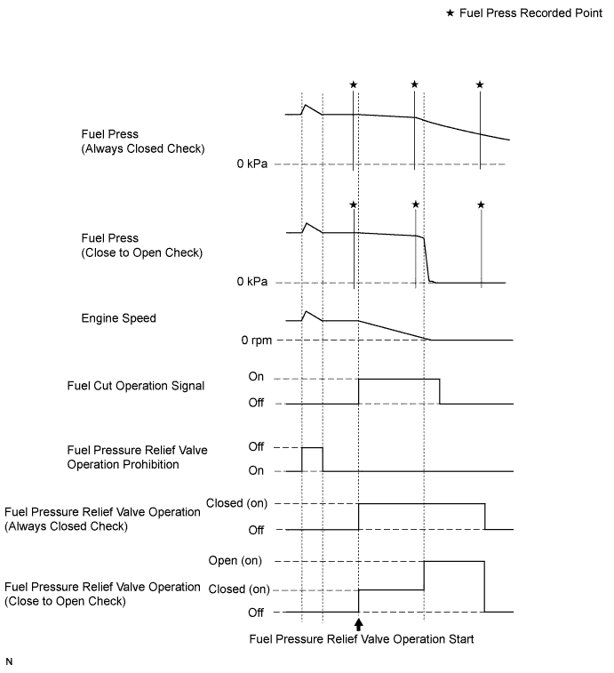
During "Pressure Discharge Valve Check", the intelligent tester measures the fuel pressure while the engine is running, after the engine is stopped, and after the pressure discharge valve operates.
-
Connect the intelligent tester to the DLC3.
-
Turn the ignition switch to ON.
-
Turn the tester on.
Note
Confirm the following conditions:
-
Engine is idling.
-
Vehicle is stopped.
-
Fuel pressure is not extremely high (less than 100000 kPa).
-
Fuel pressure sensor is normal.
-
Battery voltage is more than 8 V.
-
-
Enter the following menus: Powertrain / Engine and ECT / Utility / Pressure Discharge Valve Check.
-
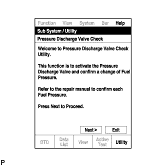
Press "Next".
-
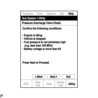
Press "Next" again to proceed.
-
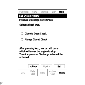
Select the "Pressure Discharge Valve Check" type.
Tech Tips
-
"Close to Open Check" opens the pressure discharge valve after the engine stops.
-
"Always Closed Check" holds the pressure discharge valve closed during the check.
-
-
Press "Next".
-
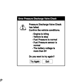
Perform troubleshooting based on the measurement results.
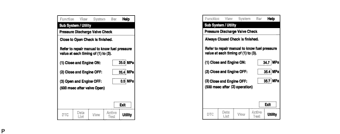
Tech Tips
-
During "Close to Open Check", if there is no large change in fuel pressure when the pressure discharge valve is closed while the engine is running and after the engine is stopped, and if the value is 0 kPa when the pressure discharge valve is open, the system is normal.
-
Perform "Always Closed Check" if the value is not 0 kPa when the pressure discharge valve is open during "Close to Open Check". If the results are the same as during "Close to Open Check", there is a pressure discharge valve operation malfunction.
-
If the fuel temperature is high, perform "Pressure Discharge Valve Check" after the fuel has cooled to the outside air temperature.
-
If a large amount of fuel is leaking, the fuel pressure decreases when the engine is stopped. However, the condition of the pressure discharge valve can still be determined by comparing the measurement results of "Close to Open Check" and "Always Closed Check".
-
-
-