AUTOMATIC TRANSMISSION SYSTEM Transmission Control Switch Circuit
| DTC Code | DTC Name |
|---|---|
| Transmission Control Switch Circuit |
DESCRIPTION
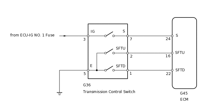
After moving the shift lever to S, it is possible to switch the shift range between "1" (S1 range) and "6" (S6 range) using the transmission control switch.
Shifting to "+" once raises the shift range by one, and shifting to "-" once lowers the shift range by one.
WIRING DIAGRAM
PROCEDURE
INSPECT TRANSMISSION CONTROL SWITCH
-
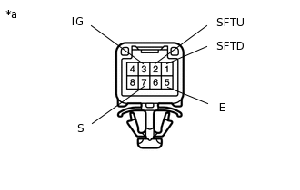
*a
Component without harness connected
(Transmission Control Switch)
Disconnect the G36 transmission control switch connector.
Measure the resistance according to the value(s) in the table below.
Standard Resistance
Tester Connection
Condition
Specified Condition
3 (IG) - 7 (S)
Shift lever in S, "+" or "-"
Below 1 Ω
2 (SFTU) - 5 (E)
Shift lever held in "+" (Up-shift)
Below 1 Ω
1 (SFTD) - 5 (E)
Shift lever held in "-" (Down-shift)
Below 1 Ω
3 (IG) - 7 (S)
Shift lever not in S, "+" or "-"
10 kΩ or higher
2 (SFTU) - 5 (E)
Shift lever in S
10 kΩ or higher
1 (SFTD) - 5 (E)
Shift lever in S
10 kΩ or higher
Result
Result
OK
NG
-
CHECK HARNESS AND CONNECTOR (TRANSMISSION CONTROL SWITCH - BATTERY, BODY GROUND)
-
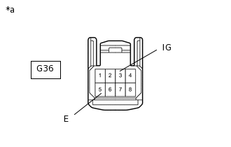
*a
Front view of wire harness connector
(to Transmission Control Switch)
Disconnect the G36 transmission control switch connector.
Measure the voltage according to the value(s) in the table below.
Standard Voltage
Tester Connection
Switch Condition
Specified Condition
G36-3 (IG) - Body ground
Engine switch on (IG)
11 to 14 V
Engine switch off
Below 1 V
Measure the resistance according to the value(s) in the table below.
Standard Resistance
Tester Connection
Condition
Specified Condition
G36-5 (E) - Body ground
Always
Below 1 Ω
Result
Result
OK
NG
NG REPAIR OR REPLACE HARNESS OR CONNECTOR
-
CHECK HARNESS AND CONNECTOR (TRANSMISSION CONTROL SWITCH - ECM)
-
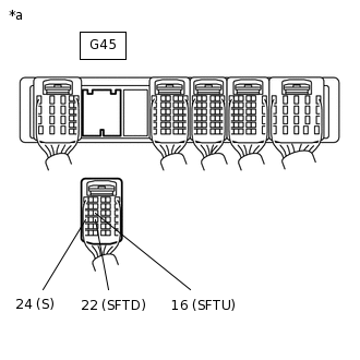
*a
Front view of wire harness connector
(to ECM)
Disconnect the G45 ECM connector.
Measure the voltage according to the value(s) in the table below.
Standard Voltage
Tester Connection
Condition
Specified Condition
G45-24 (S) - Body ground
Engine switch on (IG)
Shift lever in S, "+" or "-"
11 to 14 V
Engine switch on (IG)
Shift lever not in S, "+" or "-"
Below 1 V
Turn the engine switch off.
Measure the resistance according to the value(s) in the table below.
Standard Resistance
Tester Connection
Condition
Specified Condition
G45-16 (SFTU) - Body ground
Shift lever held in "+" (Up-shift)
Below 1 Ω
G45-22 (SFTD) - Body ground
Shift lever held in "-" (Down-shift)
Below 1 Ω
G45-16 (SFTU) - Body ground
Shift lever in S
10 kΩ or higher
G45-22 (SFTD) - Body ground
Shift lever in S
10 kΩ or higher
Result
Result
OK
NG
NG REPAIR OR REPLACE HARNESS OR CONNECTOR
-