METER / GAUGE SYSTEM Speed Signal Circuit
| DTC Code | DTC Name |
|---|---|
| Speed Signal Circuit |
DESCRIPTION
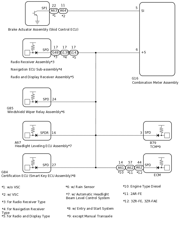
The vehicle speed signal consists of pulses sent to the combination meter assembly from the brake actuator assembly (skid control ECU).
WIRING DIAGRAM
CAUTION / NOTICE / HINT
Before replacing the certification ECU (smart key ECU assembly), refer to the Service Bulletin.
When replacing the combination meter assembly, make sure to replace it with a new one.
PROCEDURE
CHECK VEHICLE TYPE
Check vehicle type.
Result
Proceed to
for Radio Receiver Type
for Navigation Receiver Type
for Radio and Display Type
for Navigation Receiver Type CHECK NAVIGATION ECU SUB-ASSEMBLYClick here
for Radio and Display Type CHECK RADIO AND DISPLAY RECEIVER ASSEMBLYClick here
CHECK RADIO RECEIVER ASSEMBLY
*a
Front view of wire harness connector
(to Combination Meter Assembly)
*1: w/ Rain Sensor
*2: w/ Automatic Headlight Beam Level Control System
*3: w/ Entry and Start System
*4: except Manual Transaxle
*5: Engine Type Diesel
*6: Engine Type Gasoline
Disconnect the G16 combination meter assembly connector.
Disconnect the G85 windshield wiper relay assembly connector.*1
Disconnect the A67 headlight leveling ECU assembly connector.*2
Disconnect the G84 certification ECU (smart key ECU assembly) connector.*3
Disconnect the B79 TCM connector.*4
Disconnect the A61*5 or A62*6 ECM connector.
Measure the voltage according to the value(s) in the table below.
Standard Voltage
Tester Connection
Switch Condition
Specified Condition
G16-6 (+S) - Body ground
Ignition switch ON
4.5 to 14 V
Result
Proceed to
OK
NG
NG CHECK HARNESS AND CONNECTOR (COMBINATION METER ASSEMBLY - RADIO RECEIVER ASSEMBLY)Click here
CHECK WINDSHIELD WIPER RELAY ASSEMBLY
*a
Front view of wire harness connector
(to Combination Meter Assembly)
Note:For vehicle without a rain sensor, proceed to next step.
*1: for Radio Receiver Type
*2: for Navigation Receiver Type
*3: for Radio and Display Type
*4: w/ Automatic Headlight Beam Level Control System
*5: w/ Entry and Start System
*6: except Manual Transaxle
*7: Engine Type Diesel
*8: Engine Type Gasoline
Disconnect the G16 combination meter assembly connector.
Disconnect the G48 radio receiver assembly connector.*1
Disconnect the G139 navigation ECU sub-assembly connector.*2
Disconnect the G143 radio and display receiver assembly connector.*3
Disconnect the A67 headlight leveling ECU assembly connector.*4
Disconnect the G84 certification ECU (smart key ECU assembly) connector.*5
Disconnect the B79 TCM connector.*6
Disconnect the A61*7 or A62*8 ECM connector.
Measure the voltage according to the value(s) in the table below.
Standard Voltage
Tester Connection
Switch Condition
Specified Condition
G16-6 (+S) - Body ground
Ignition switch ON
4.5 to 14 V
Result
Proceed to
OK
NG
NG CHECK HARNESS AND CONNECTOR (COMBINATION METER ASSEMBLY - WINDSHIELD WIPER RELAY ASSEMBLY)Click here
CHECK HEADLIGHT LEVELING ECU ASSEMBLY
*a
Front view of wire harness connector
(to Combination Meter Assembly)
Note:For vehicle without an automatic headlight beam level control system, proceed to next step.
*1: for Radio Receiver Type
*2: for Navigation Receiver Type
*3: for Radio and Display Type
*4: w/ Rain Sensor
*5: w/ Entry and Start System
*6: except Manual Transaxle
*7: Engine Type Diesel
*8: Engine Type Gasoline
Disconnect the G16 combination meter assembly connector.
Disconnect the G48 radio receiver assembly connector.*1
Disconnect the G139 navigation ECU sub-assembly connector.*2
Disconnect the G143 radio and display receiver assembly connector.*3
Disconnect the G85 windshield wiper relay assembly connector.*4
Disconnect the G84 certification ECU (smart key ECU assembly) connector.*5
Disconnect the B79 TCM connector.*6
Disconnect the A61*7 or A62*8 ECM connector.
Measure the voltage according to the value(s) in the table below.
Standard Voltage
Tester Connection
Switch Condition
Specified Condition
G16-6 (+S) - Body ground
Ignition switch ON
4.5 to 14 V
Result
Proceed to
OK
NG
NG CHECK HARNESS AND CONNECTOR (COMBINATION METER ASSEMBLY - HEADLIGHT LEVELING ECU)Click here
CHECK CERTIFICATION ECU (SMART KEY ECU ASSEMBLY)
*a
Front view of wire harness connector
(to Combination Meter Assembly)
Note:For vehicle without an entry and start system, proceed to next step.
*1: for Radio Receiver Type
*2: for Navigation Receiver Type
*3: for Radio and Display Type
*4: w/ Rain Sensor
*5: w/ Automatic Headlight Beam Level Control System
*6: except Manual Transaxle
*7: Engine Type Diesel
*8: Engine Type Gasoline
Disconnect the G16 combination meter assembly connector.
Disconnect the G48 radio receiver assembly connector.*1
Disconnect the G139 navigation ECU sub-assembly connector.*2
Disconnect the G143 radio and display receiver assembly connector.*3
Disconnect the G85 windshield wiper relay assembly connector.*4
Disconnect the A67 headlight leveling ECU assembly connector.*5
Disconnect the B79 TCM connector.*6
Disconnect the A61*7 or A62*8 ECM connector.
Measure the voltage according to the value(s) in the table below.
Standard Voltage
Tester Connection
Switch Condition
Specified Condition
G16-6 (+S) - Body ground
Ignition switch ON
4.5 to 14 V
Result
Proceed to
OK
NG
NG CHECK HARNESS AND CONNECTOR (COMBINATION METER ASSEMBLY - CERTIFICATION ECU [SMART KEY ECU ASSEMBLY])Click here
CHECK TCM
*a
Front view of wire harness connector
(to Combination Meter Assembly)
Note:For vehicle manual transaxle, proceed to next step.
*1: for Radio Receiver Type
*2: for Navigation Receiver Type
*3: for Radio and Display Type
*4: w/ Rain Sensor
*5: w/ Automatic Headlight Beam Level Control System
*6: w/ Entry and Start System
*7: Engine Type Diesel
*8: Engine Type Gasoline
Disconnect the G16 combination meter assembly connector.
Disconnect the G48 radio receiver assembly connector.*1
Disconnect the G139 navigation ECU sub-assembly connector.*2
Disconnect the G143 radio and display receiver assembly connector.*3
Disconnect the G85 windshield wiper relay assembly connector.*4
Disconnect the A67 headlight leveling ECU assembly connector.*5
Disconnect the G84 certification ECU (smart key ECU assembly) connector.*6
Disconnect the A61*7 or A62*8 ECM connector.
Measure the voltage according to the value(s) in the table below.
Standard Voltage
Tester Connection
Switch Condition
Specified Condition
G16-6 (+S) - Body ground
Ignition switch ON
4.5 to 14 V
Result
Proceed to
OK
NG
NG CHECK HARNESS AND CONNECTOR (COMBINATION METER ASSEMBLY - CERTIFICATION ECU [SMART KEY ECU ASSEMBLY])Click here
CHECK ECM
*a
Front view of wire harness connector
(to Combination Meter Assembly)
*1: for Radio Receiver Type
*2: for Navigation Receiver Type
*3: for Radio and Display Type
*4: w/ Rain Sensor
*5: w/ Automatic Headlight Beam Level Control System
*6: w/ Entry and Start System
*7: except Manual Transaxle
Disconnect the G16 combination meter assembly connector.
Disconnect the G48 radio receiver assembly connector.*1
Disconnect the G139 navigation ECU sub-assembly connector.*2
Disconnect the G143 radio and display receiver assembly connector.*3
Disconnect the G85 windshield wiper relay assembly connector.*4
Disconnect the A67 headlight leveling ECU assembly connector.*5
Disconnect the G84 certification ECU (smart key ECU assembly) connector.*6
Disconnect the B79 TCM connector.*7
Measure the voltage according to the value(s) in the table below.
Standard Voltage
Tester Connection
Switch Condition
Specified Condition
G16-6 (+S) - Body ground
Ignition switch ON
4.5 to 14 V
Result
Proceed to
OK
NG
NG CHECK HARNESS AND CONNECTOR (COMBINATION METER ASSEMBLY - CERTIFICATION ECU [SMART KEY ECU ASSEMBLY])Click here
CHECK COMBINATION METER ASSEMBLY (OUTPUT VOLTAGE)
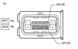
*A
w/o VSC
*B
w/ VSC
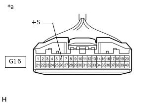
*a
Front view of wire harness connector
(to Brake Actuator Assembly (Skid Control ECU))
*1: w/o VSC
*2: w/VSC
Disconnect the A63*1 or A64*2 brake actuator assembly (skid control ECU) connector.
Measure the voltage according to the value(s) in the table below.
Standard Voltage
Table 1. w/o VSC Tester Connection
Switch Condition
Specified Condition
A63-22 (SP1) - Body ground
Ignition switch ON
11 to 14 V
Table 2. w/ VSC Tester Connection
Switch Condition
Specified Condition
A64-11 (SP1) - Body ground
Ignition switch ON
11 to 14 V
Result
Proceed to
OK
NG
NG CHECK HARNESS AND CONNECTOR (COMBINATION METER ASSEMBLY - BRAKE ACTUATOR ASSEMBLY [SKID CONTROL ECU])Click here
CHECK COMBINATION METER ASSEMBLY (SPEED SIGNAL)
Remove the combination meter assembly with the connector(s) still connected.
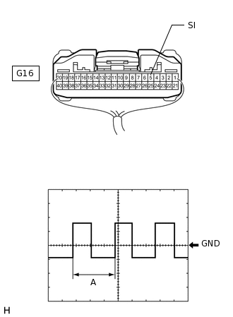
Connect an oscilloscope to terminal G16-5 (SI) and body ground.
Check the signal waveform according to the condition(s) in the table below.
Table 3. Measurement Condition Item
Condition
Tester Connection
G16-5 (SI) - Body ground
Tool Setting
5 V/DIV., 20 ms./DIV.
Vehicle Condition
Driving at approximately 20 km/h (12 mph)
Tip:When the system is functioning normally, one wheel revolution generates 4 pulses. As the vehicle speed increases, the width indicated by A in the illustration narrows.
OK
The waveform displayed is as shown in the illustration.
Result
Proceed to
OK
NG (w/o VSC)
NG (w/ VSC)
CHECK NAVIGATION ECU SUB-ASSEMBLY
*a
Front view of wire harness connector
(to Combination Meter Assembly)
*1: w/ Rain Sensor
*2: w/ Automatic Headlight Beam Level Control System
*3: w/ Entry and Start System
*4: except Manual Transaxle
*5: Engine Type Diesel
*6: Engine Type Gasoline
Disconnect the G16 combination meter assembly connector.
Disconnect the G85 windshield wiper relay assembly connector.*1
Disconnect the A67 headlight leveling ECU assembly connector.*2
Disconnect the G84 certification ECU (smart key ECU assembly) connector.*3
Disconnect the B79 TCM connector.*4
Disconnect the A61*5 or A62*6 ECM connector.
Measure the voltage according to the value(s) in the table below.
Standard Voltage
Tester Connection
Switch Condition
Specified Condition
G16-6 (+S) - Body ground
Ignition switch ON
4.5 to 14 V
Result
Proceed to
OK
NG
OK CHECK WINDSHIELD WIPER RELAY ASSEMBLYClick here
NG CHECK HARNESS AND CONNECTOR (COMBINATION METER ASSEMBLY - NAVIGATION ECU SUB-ASSEMBLY)Click here
CHECK HARNESS AND CONNECTOR (COMBINATION METER ASSEMBLY - RADIO RECEIVER ASSEMBLY)
*1: w/ Rain Sensor
*2: w/ Automatic Headlight Beam Level Control System
*3: w/ Entry and Start System
*4: except Manual Transaxle
*5: Engine Type Diesel
*6: Engine Type Gasoline
Disconnect the G16 combination meter assembly connector.
Disconnect the G48 radio receiver assembly connector.
Disconnect the G85 windshield wiper relay assembly connector.*1
Disconnect the A67 headlight leveling ECU assembly connector.*2
Disconnect the G84 certification ECU (smart key ECU assembly) connector.*3
Disconnect the B79 TCM connector.*4
Disconnect the A61*5 or A62*6 ECM connector.
Measure the resistance according to the value(s) in the table below.
Standard Resistance
Tester Connection
Condition
Specified Condition
G16-6 (+S) - G48-17 (SP1)
Always
Below 1 Ω
G16-6 (+S) or G48-17 (SP1) - Body ground
Always
10 kΩ or higher
Result
Proceed to
OK
NG
NG REPAIR OR REPLACE HARNESS OR CONNECTOR
CHECK HARNESS AND CONNECTOR (COMBINATION METER ASSEMBLY - WINDSHIELD WIPER RELAY ASSEMBLY)
*1: for Radio Receiver Type
*2: for Navigation Receiver Type
*3: for Radio and Display Type
*4: w/ Automatic Headlight Beam Level Control System
*5: w/ Entry and Start System
*6: except Manual Transaxle
*7: Engine Type Diesel
*8: Engine Type Gasoline
Disconnect the G16 combination meter assembly connector.
Disconnect the G85 windshield wiper relay assembly connector.
Disconnect the G48 radio receiver assembly connector.*1
Disconnect the G139 navigation ECU sub-assembly connector.*2
Disconnect the G143 radio and display receiver assembly connector.*3
Disconnect the A67 headlight leveling ECU assembly connector.*4
Disconnect the G84 certification ECU (smart key ECU assembly) connector.*5
Disconnect the B79 TCM connector.*6
Disconnect the A61*7 or A62*8 ECM connector.
Measure the resistance according to the value(s) in the table below.
Standard Resistance
Tester Connection
Condition
Specified Condition
G16-6 (+S) - G85-24 (SPD)
Always
Below 1 Ω
G16-6 (+S) or G85-24 (SPD) - Body ground
Always
10 kΩ or higher
Result
Proceed to
OK
NG
NG REPAIR OR REPLACE HARNESS OR CONNECTOR
CHECK HARNESS AND CONNECTOR (COMBINATION METER ASSEMBLY - HEADLIGHT LEVELING ECU)
*1: for Radio Receiver Type
*2: for Navigation Receiver Type
*3: for Radio and Display Type
*4: w/ Rain Sensor
*5: w/ Entry and Start System
*6: except Manual Transaxle
*7: Engine Type Diesel
*8: Engine Type Gasoline
Disconnect the G16 combination meter assembly connector.
Disconnect the A67 headlight leveling ECU assembly connector.
Disconnect the G48 radio receiver assembly connector.*1
Disconnect the G139 navigation ECU sub-assembly connector.*2
Disconnect the G143 radio and display receiver assembly connector.*3
Disconnect the G85 windshield wiper relay assembly connector.*4
Disconnect the G84 certification ECU (smart key ECU assembly) connector.*5
Disconnect the B79 TCM connector.*6
Disconnect the A61*7 or A62*8 ECM connector.
Measure the resistance according to the value(s) in the table below.
Standard Resistance
Tester Connection
Condition
Specified Condition
G16-6 (+S) - A67-16 (SPDR)
Always
Below 1 Ω
G16-6 (+S) or A67-16 (SPDR) - Body ground
Always
10 kΩ or higher
Result
Proceed to
OK
NG
NG REPAIR OR REPLACE HARNESS OR CONNECTOR
CHECK HARNESS AND CONNECTOR (COMBINATION METER ASSEMBLY - CERTIFICATION ECU [SMART KEY ECU ASSEMBLY])
*1: for Radio Receiver Type
*2: for Navigation Receiver Type
*3: for Radio and Display Type
*4: w/ Rain Sensor
*5: w/ Automatic Headlight Beam Level Control System
*6: except Manual Transaxle
*7: Engine Type Diesel
*8: Engine Type Gasoline
Disconnect the G16 combination meter assembly connector.
Disconnect the G84 certification ECU (smart key ECU assembly) connector.
Disconnect the G48 radio receiver assembly connector.*1
Disconnect the G139 navigation ECU sub-assembly connector.*2
Disconnect the G143 radio and display receiver assembly connector.*3
Disconnect the G85 windshield wiper relay assembly connector.*4
Disconnect the A67 headlight leveling ECU assembly connector.*5
Disconnect the B79 TCM connector.*6
Disconnect the A61*7 or A62*8 ECM connector.
Measure the resistance according to the value(s) in the table below.
Standard Resistance
Tester Connection
Condition
Specified Condition
G16-6 (+S) - A67-16 (SPDR)
Always
Below 1 Ω
G16-6 (+S) or A67-16 (SPDR) - Body ground
Always
10 kΩ or higher
Result
Proceed to
OK
NG
OK REPLACE CERTIFICATION ECU (SMART KEY ECU ASSEMBLY)
NG REPAIR OR REPLACE HARNESS OR CONNECTOR
CHECK HARNESS AND CONNECTOR (COMBINATION METER ASSEMBLY - CERTIFICATION ECU [SMART KEY ECU ASSEMBLY])
*1: for Radio Receiver Type
*2: for Navigation Receiver Type
*3: for Radio and Display Type
*4: w/ Rain Sensor
*5: w/ Automatic Headlight Beam Level Control System
*6: w/ Entry and Start System
*7: Engine Type Diesel
*8: Engine Type Gasoline
Disconnect the G16 combination meter assembly connector.
Disconnect the B79 TCM connector.
Disconnect the G48 radio receiver assembly connector.*1
Disconnect the G139 navigation ECU sub-assembly connector.*2
Disconnect the G143 radio and display receiver assembly connector.*3
Disconnect the G85 windshield wiper relay assembly connector.*4
Disconnect the A67 headlight leveling ECU assembly connector.*5
Disconnect the G84 certification ECU (smart key ECU assembly) connector.*6
Disconnect the A61*7 or A62*8 ECM connector.
Measure the resistance according to the value(s) in the table below.
Standard Resistance
Tester Connection
Condition
Specified Condition
G16-6 (+S) - B79-3 (SPD)
Always
Below 1 Ω
G16-6 (+S) or B79-3 (SPD) - Body ground
Always
10 kΩ or higher
Result
Proceed to
OK (U660F)
OK (U760E)
OK (U760F)
OK (K111)
OK (K111F)
NG
NG REPAIR OR REPLACE HARNESS OR CONNECTOR
CHECK HARNESS AND CONNECTOR (COMBINATION METER ASSEMBLY - CERTIFICATION ECU [SMART KEY ECU ASSEMBLY])
*1: Engine Type Diesel
*2: Engine Type Gasoline
*3: for Radio Receiver Type
*4: for Navigation Receiver Type
*5: for Radio and Display Type
*6: w/ Rain Sensor
*7: w/ Automatic Headlight Beam Level Control System
*8: w/ Entry and Start System
*9: except Manual Transaxle
Disconnect the G16 combination meter assembly connector.
Disconnect the A61*1 or A62*2 ECM connector.
Disconnect the G48 radio receiver assembly connector.*3
Disconnect the G139 navigation ECU sub-assembly connector.*4
Disconnect the G143 radio and display receiver assembly connector.*5
Disconnect the G85 windshield wiper relay assembly connector.*6
Disconnect the A67 headlight leveling ECU assembly connector.*7
Disconnect the G84 certification ECU (smart key ECU assembly) connector.*8
Disconnect the B79 TCM connector.*9
Measure the resistance according to the value(s) in the table below.
Standard Resistance
Table 4. Engine Type Diesel Tester Connection
Condition
Specified Condition
G16-6 (+S) - A61-14 (SPD)
Always
Below 1 Ω
G16-6 (+S) or A61-14 (SPD) - Body ground
Always
10 kΩ or higher
Table 5. 2AR-FE Tester Connection
Condition
Specified Condition
G16-6 (+S) - A62-57 (SPD)
Always
Below 1 Ω
G16-6 (+S) or A62-57 (SPD) - Body ground
Always
10 kΩ or higher
Table 6. 3ZR-FE, 3ZR-FAE Tester Connection
Condition
Specified Condition
G16-6 (+S) - A62-44 (SPD)
Always
Below 1 Ω
G16-6 (+S) or A62-44 (SPD) - Body ground
Always
10 kΩ or higher
Result
Proceed to
OK (1AD-FTV)
OK (2AD-FHV)
OK (2AD-FTV)
OK (2AR-FE)
OK (3ZR-FAE)
OK (3ZR-FE)
NG
NG REPAIR OR REPLACE HARNESS OR CONNECTOR
CHECK HARNESS AND CONNECTOR (COMBINATION METER ASSEMBLY - BRAKE ACTUATOR ASSEMBLY [SKID CONTROL ECU])
Disconnect the G16 combination meter assembly connector.
Disconnect the A63*1 or A64*2 brake actuator assembly (skid control ECU) connector.
Measure the resistance according to the value(s) in the table below.
Standard Resistance
Table 7. w/o VSC Tester Connection
Condition
Specified Condition
G16-5 (SI) - A63-22 (SP1)
Always
Below 1 Ω
G16-5 (SI) or A63-22 (SP1) - Body ground
Always
10 kΩ or higher
Table 8. w/ VSC Tester Connection
Condition
Specified Condition
G16-5 (SI) - A64-11 (SP1)
Always
Below 1 Ω
G16-5 (SI) or A64-11 (SP1) - Body ground
Always
10 kΩ or higher
Result
Proceed to
OK
NG
NG REPAIR OR REPLACE HARNESS OR CONNECTOR
CHECK RADIO AND DISPLAY RECEIVER ASSEMBLY
*a
Front view of wire harness connector
(to Combination Meter Assembly)
*1: w/ Rain Sensor
*2: w/ Automatic Headlight Beam Level Control System
*3: w/ Entry and Start System
*4: except Manual Transaxle
*5: Engine Type Diesel
*6: Engine Type Gasoline
Disconnect the G16 combination meter assembly connector.
Disconnect the G85 windshield wiper relay assembly connector.*1
Disconnect the A67 headlight leveling ECU assembly connector.*2
Disconnect the G84 certification ECU (smart key ECU assembly) connector.*3
Disconnect the B79 TCM connector.*4
Disconnect the A61*5 or A62*6 ECM connector.
Measure the voltage according to the value(s) in the table below.
Standard Voltage
Tester Connection
Switch Condition
Specified Condition
G16-6 (+S) - Body ground
Ignition switch ON
4.5 to 14 V
Result
Proceed to
OK
NG
OK CHECK WINDSHIELD WIPER RELAY ASSEMBLYClick here
NG CHECK HARNESS AND CONNECTOR (COMBINATION METER ASSEMBLY - RADIO AND DISPLAY RECEIVER ASSEMBLY)Click here
CHECK HARNESS AND CONNECTOR (COMBINATION METER ASSEMBLY - NAVIGATION ECU SUB-ASSEMBLY)
*1: w/ Rain Sensor
*2: w/ Automatic Headlight Beam Level Control System
*3: w/ Entry and Start System
*4: except Manual Transaxle
*5: Engine Type Diesel
*6: Engine Type Gasoline
Disconnect the G16 combination meter assembly connector.
Disconnect the G139 navigation receiver assembly connector.
Disconnect the G85 windshield wiper relay assembly connector.*1
Disconnect the A67 headlight leveling ECU assembly connector.*2
Disconnect the G84 certification ECU (smart key ECU assembly) connector.*3
Disconnect the B79 TCM connector.*4
Disconnect the A61*5 or A62*6 ECM connector.
Measure the resistance according to the value(s) in the table below.
Standard Resistance
Tester Connection
Condition
Specified Condition
G16-6 (+S) - G139-17 (SP1)
Always
Below 1 Ω
G16-6 (+S) or G4139-17 (SP1) - Body ground
Always
10 kΩ or higher
Result
Proceed to
OK
NG
NG REPAIR OR REPLACE HARNESS OR CONNECTOR
CHECK HARNESS AND CONNECTOR (COMBINATION METER ASSEMBLY - RADIO AND DISPLAY RECEIVER ASSEMBLY)
*1: w/ Rain Sensor
*2: w/ Automatic Headlight Beam Level Control System
*3: w/ Entry and Start System
*4: except Manual Transaxle
*5: Engine Type Diesel
*6: Engine Type Gasoline
Disconnect the G16 combination meter assembly connector.
Disconnect the G143 radio and display receiver assembly connector.
Disconnect the G85 windshield wiper relay assembly connector.*1
Disconnect the A67 headlight leveling ECU assembly connector.*2
Disconnect the G84 certification ECU (smart key ECU assembly) connector.*3
Disconnect the B79 TCM connector.*4
Disconnect the A61*5 or A62*6 ECM connector.
Measure the resistance according to the value(s) in the table below.
Standard Resistance
Tester Connection
Condition
Specified Condition
G16-6 (+S) - G143-17 (SP1)
Always
Below 1 Ω
G16-6 (+S) or G4143-17 (SP1) - Body ground
Always
10 kΩ or higher
Result
Proceed to
OK
NG
NG REPAIR OR REPLACE HARNESS OR CONNECTOR