ECD SYSTEM(for Swirl Control Valve), Diagnostic DTC:P0045
| DTC Code | DTC Name |
|---|---|
| P0045 | Turbocharger / Supercharger Boost Control "A" Circuit / Open |
DESCRIPTION
Turbo pressure is controlled through the use of variable turbine geometry equipped to the turbocharger. Adjustable guide vanes are installed to the outside of the turbine wheel on the exhaust side.
A DC motor is used to drive and change the angle of the guide vanes. This adjusts the amount of exhaust gas added to the turbine and changes the drive torque of the turbine wheel. As a result, the boost pressure is adjusted as needed.
DTC No. |
DTC Detection Condition |
Trouble Area |
|---|---|---|
P0045 |
Open in DC motor (turbocharger sub-assembly) circuit for 0.22 seconds. (1 trip detection logic) |
|
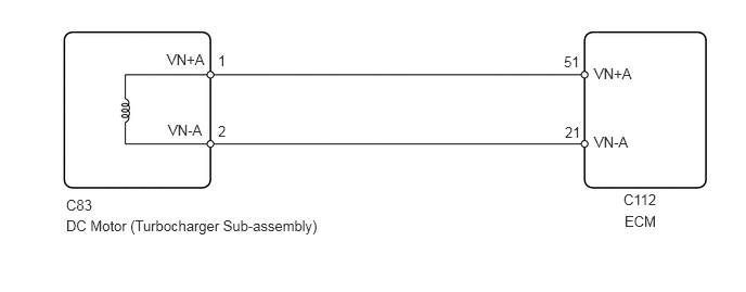
WIRING DIAGRAM
CAUTION / NOTICE / HINT
When replacing the ECM, the ECM needs Registration and Initialization (Click here).
When the ECM must be replaced, before replacing the ECM, perform the "Learning Values Save" function using the GTS. Then after installing the new ECM, perform all of the initialization/registrations for the "Learning Values Write" function by following the instructions shown on the GTS display.
Read freeze frame data using the GTS. Freeze frame data records the engine condition when malfunctions are detected. When troubleshooting, freeze frame data can help determine if the vehicle was moving or stationary, if the engine was warmed up or not, and other data from the time the malfunction occurred.
PROCEDURE
CHECK HARNESS AND CONNECTOR (DC MOTOR - ECM)
Disconnect the DC motor connector.
Disconnect the ECM connector.
Measure the resistance according to the value(s) in the table below.
Standard Resistance
Tester Connection
Condition
Specified Condition
C83-1 (VN+A) - C112-51 (VN+A)
Always
Below 1 Ω
C83-2 (VN-A) - C112-21 (VN-A)
Always
Below 1 Ω
C83-1 (VN+A) or C112-51 (VN+A) - Body ground
Always
10 kΩ or higher
C83-2 (VN-A) or C112-21 (VN-A) - Body ground
Always
10 kΩ or higher
REPAIR OR REPLACE HARNESS OR CONNECTORClick here
INSPECT TURBOCHARGER SUB-ASSEMBLY (DC MOTOR)
Disconnect the turbocharger sub-assembly connector.
Measure the resistance according to the value(s) in the table below.
Standard Resistance
Tester Connection
Condition
Specified Condition
1 (VN+A) - 2 (VN-A)
Always
0.3 to 100 Ω
REPLACE TURBOCHARGER SUB-ASSEMBLYClick here
REPLACE ECM
Replace the ECM (Click here).
CONFIRM WHETHER MALFUNCTION HAS BEEN SUCCESSFULLY REPAIREDClick here
REPAIR OR REPLACE HARNESS OR CONNECTOR
Repair or replace the harness or connector.
CONFIRM WHETHER MALFUNCTION HAS BEEN SUCCESSFULLY REPAIREDClick here
REPLACE TURBOCHARGER SUB-ASSEMBLY
Replace the turbocharger sub-assembly (Click here).
CONFIRM WHETHER MALFUNCTION HAS BEEN SUCCESSFULLY REPAIRED
Connect the GTS to the DLC3.
Turn the ignition switch to ON and turn the GTS on.
Clear the DTCs (Click here).
Turn the ignition switch off and wait for 60 seconds or more [A].
Perform road test [B].
Repeat [A] and [B] for the number of trips detected.
Enter the following menus: Powertrain / Engine and ECT / Trouble Codes.
Confirm that the DTC is not output again.
END