AUTOMATIC TRANSMISSION SYSTEM Shift Paddle Switch Circuit
DESCRIPTION
When the shift lever is in M, it is possible to change into any gear using the steering assembly transmission shift switch.
Additionally, when the vehicle is being driving with the shift lever in D, operating the steering assembly transmission shift switch changes to selection of gears with the shift lever in D, enabling shifting to any gear.
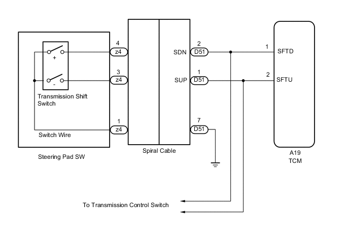
WIRING DIAGRAM
PROCEDURE
-
READ VALUE USING GTS
-
Connect the GTS to the DLC3.
-
Turn the ignition switch to ON.
-
Read the value displayed on the GTS.
OK Tester Display Condition Standard Sport Shift Up SW Continuously shift to "+" (upshift): ON
Release "+" (up-shift): OFF
- Sport Shift Down SW Continuously shift to "-" (down-shift): ON
Release "-" (down-shift): OFF
-
OK 
CHECK INTERMITTENT PROBLEMS Click here
NG 
-
-
CHECK HARNESS AND CONNECTOR (TRANSMISSION SHIFT SWITCH - TCM)
-
Disconnect the TCM connector.
-
Measure the resistance according to the value(s) in the table below.
Standard resistance Tester Connection Condition Specified Condition A19-1(SFTD) - Body ground Pull continuously
"+"
(Up shift)
Below 1 Ω Release "+" or "-" 10 kΩ or higher A19-2(SFTU) - Body ground Pull continuously
"-"
(Down shift)
Below 1 Ω Release "+" or "-" 10 kΩ or higher -
Connect the TCM connector.
NG 
CHECK HARNESS AND CONNECTOR (SPIRAL CABLE - BODY GROUND) Click here
OK
-
-
REPLACE TCM
-
Replace the TCM Click here.
NEXT
PERFORM THE RESET MEMORY Click here
-
-
CHECK HARNESS AND CONNECTOR (SPIRAL CABLE - BODY GROUND)
-
Disconnect the spiral cable connector.
-
Measure the resistance according to the value(s) in the table below.
Standard resistance Tester Connection Condition Specified Condition D51-7 - Body ground Always Below 1 Ω -
Connect the spiral cable connector.
NG
REPAIR OR REPLACE HARNESS OR CONNECTOR
OK
-
-
CHECK HARNESS AND CONNECTOR (SPIRAL CABLE - TCM)
-
Disconnect the TCM connector.
-
Disconnect the spiral cable connector.
-
Measure the resistance according to the value(s) in the table below.
Standard resistance Tester Connection Condition Specified Condition A19-1(SFTD) - D51-2 Always Below 1 Ω A19-2(SFTU) - D51-1 Always Below 1 Ω A19-1(SFTD) or D51-2 - Body ground Always 10 kΩ or higher A19-2(SFTU) or D51-1 - Body ground Always 10 kΩ or higher -
Connect the TCM connector.
-
Connect the spiral cable connector.
NG
REPAIR OR REPLACE HARNESS OR CONNECTOR
OK
-
-
CHECK TRANSMISSION SHIFT SWITCH (TRANSMISSION SHIFT SWITCH - SPIRAL CABLE)
-
Disconnect the spiral cable connector.
-
Measure the resistance according to the value(s) in the table below.
Standard resistance Tester Connection Condition Specified Condition z4-4 - z4-1 Pull continuously
"+"
(Up shift)
Below 1 Ω Release "+" or "-" 10 kΩ or higher z4-3 - z4-1 Pull continuously
"-"
(Down shift)
Below 1 Ω Release "+" or "-" 10 kΩ or higher -
Connect the spiral cable connector.
OK
INSPECT SPIRAL CABLE SUB-ASSEMBLY Click here
NG
-
-
INSPECT TRANSMISSION SHIFT SWITCH ASSEMBLY
-
Inspect the transmission shift switch assembly Click here.
OK
REPLACE SWITCH NO.1 WIRE Click here
NG
REPLACE TRANSMISSION SHIFT SWITCH ASSEMBLY Click here
-