EXHAUST GAS TEMPERATURE SENSOR(w/o Glow Plug Controller) INSTALLATION
PROCEDURE
INSTALL NO. 2 EXHAUST GAS TEMPERATURE SENSOR
Note:If the No. 2 exhaust gas temperature sensor is dropped, replace it with a new one.
-
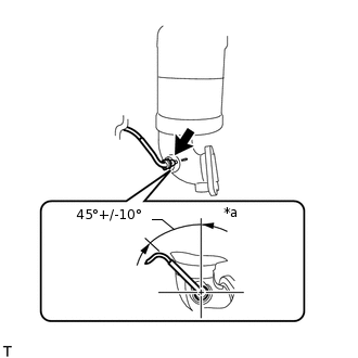
*a
Upper
Using a 14 mm union nut wrench, install the No. 2 exhaust gas temperature sensor to the exhaust manifold converter sub-assembly.
30 N*m
306 kgf*cm
22 ft.*lbf
Note:Use the formula to calculate special torque values for situations where a union nut wrench is combined with a torque wrench.
Install the No. 2 exhaust gas temperature sensor within the area shown in the illustration.
-
INSTALL EXHAUST GAS TEMPERATURE SENSOR
Note:If the exhaust gas temperature sensor is dropped, replace it with a new one.
-
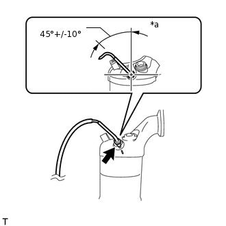
*a
Upper
Using a 14 mm union nut wrench, install the exhaust gas temperature sensor to the exhaust manifold converter sub-assembly.
30 N*m
306 kgf*cm
22 ft.*lbf
Note:Use the formula to calculate special torque values for situations where a union nut wrench is combined with a torque wrench.
Install the exhaust gas temperature sensor within the area shown in the illustration.
-
INSTALL EXHAUST MANIFOLD CONVERTER SUB-ASSEMBLY