OUTER REAR VIEW MIRROR REMOVAL
Tech Tips
-
Use the same procedure for RHD and LHD vehicles.
-
The procedure listed below is for LHD vehicles.
-
Use the same procedure for the RH and LH sides.
-
The procedure listed below is for the LH side.
-
REMOVE POWER WINDOW REGULATOR MASTER SWITCH ASSEMBLY WITH FRONT DOOR ARMREST BASE PANEL LH (w/ Power Window)
-
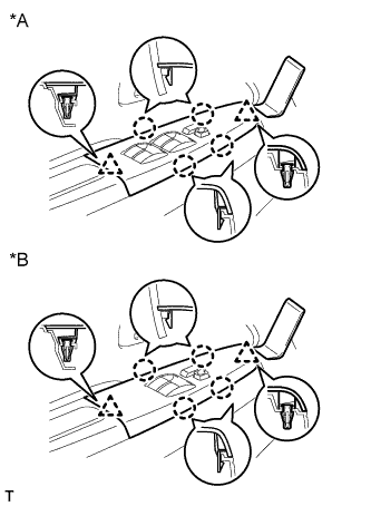
Text in Illustration *A for Double Cab *B for Single Cab, for Extra Cab Using a moulding remover, detach the 2 clips.
-
Disconnect the 4 claws and remove the power window regulator master switch assembly with front door armrest base panel.
-
-
REMOVE POWER WINDOW REGULATOR SWITCH ASSEMBLY WITH FRONT DOOR ARMREST BASE PANEL RH (w/ Power Window)
-
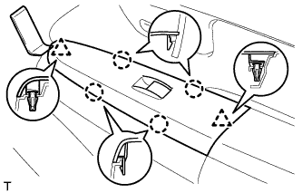
Using a moulding remover, detach the 2 clips.
-
Disconnect the 4 claws and remove the power window regulator switch assembly with front door armrest base panel.
-
-
REMOVE FRONT DOOR WINDOW REGULATOR HANDLE ASSEMBLY (w/o Power Window)
-
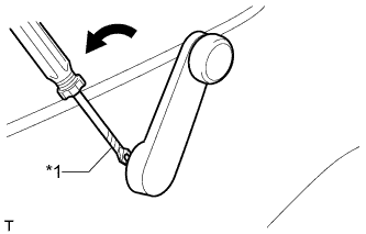
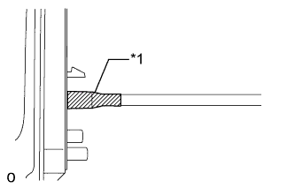
Text in Illustration *1 Protective Tape Insert a clip remover between the plate and trim board.
Tech Tips
Tape the clip remover tip before use.
-
Turn the handle counterclockwise to remove the snap ring, front door window regulator handle and plate.
-
-
REMOVE FRONT DOOR LOWER FRAME BRACKET GARNISH LH
-
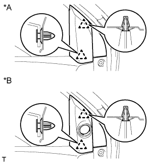
Text in Illustration *A w/o Front No. 2 Speaker *B w/ Front No. 2 Speaker Detach the 2 clips and remove the front door lower frame bracket garnish.
-
-
REMOVE DOOR PULL HANDLE
-
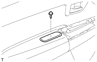
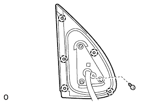
Remove the screw and door pull handle.
-
-
REMOVE FRONT DOOR TRIM BOARD SUB-ASSEMBLY LH
-
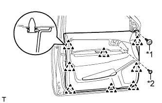
Text in Illustration *1 Clip *2 Screw for Double Cab:
-
Remove the clip and screw.
-
Detach the 8 clips and remove the front door trim board.
-
-
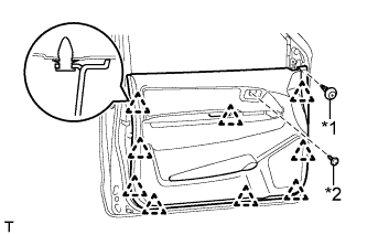
Text in Illustration *1 Clip *2 Screw for Single Cab, for Extra Cab:
-
Remove the clip and screw.
-
Detach the 9 clips and remove the front door trim board.
-
-
-
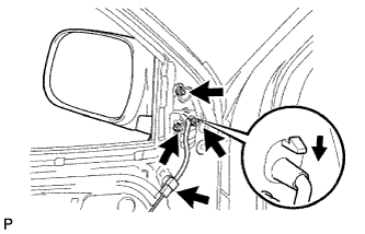
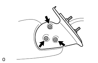
REMOVE OUTER REAR VIEW MIRROR ASSEMBLY LH
-
w/ Power Mirror Control System:
Disconnect the mirror connector.
-
Remove the 3 nuts.
-
Push down the claw and remove the outer rear view mirror assembly LH.
-
-
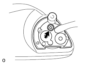
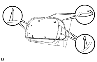
REMOVE OUTER MIRROR LH
-
Using a screwdriver, detach the 2 claws as shown in the illustration.
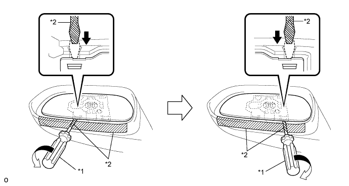
Text in Illustration *1 Screwdriver *2 Protective Tape Note
Do not pull the outer mirror LH with excessive force. Doing so may cause the actuator to come off or break the mirror surface.
Tech Tips
Apply protective tape to the mirror body and screwdriver tip.
-
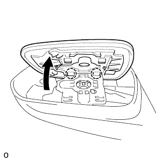
Detach the 2 claws at the upper part of the outer mirror.
-
Remove the outer mirror LH.
-
-
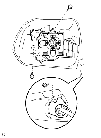
REMOVE OUTER MIRROR COVER LH (w/ Side Turn Signal Light)
-
Text in Illustration *1 Tape Remove the tape.
-
Remove the screw, detach the 5 claws and remove the rubber base.
Tech Tips
It is not necessary to completely remove the rubber base. Slightly move the rubber base so that the outer mirror cover LH can be removed in a later step.
-
Using a T25 "TORX" socket wrench, remove the 3 screws.
-
Using a T25 "TORX" socket wrench, remove the screw.
-
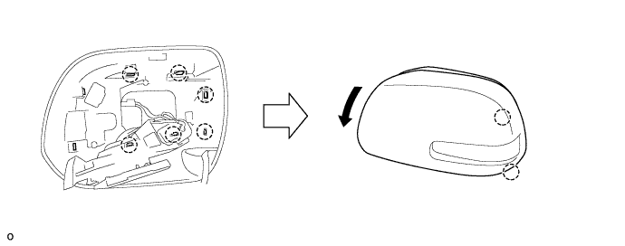
Remove the 3 screws.
-
Detach the 6 claws.
-
Detach the 2 claws and remove the outer mirror cover LH as shown in the illustration.
-
-
REMOVE OUTER MIRROR COVER LH (w/o Side Turn Signal Light)
-
Using a screwdriver, detach the 6 claws.
Tech Tips
Tape the screwdriver tip before use.
-
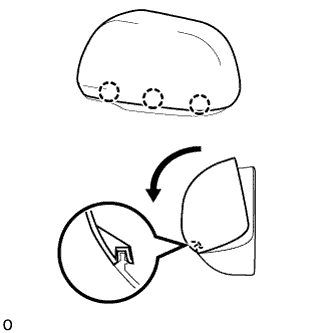
Detach the 3 claws as shown in the illustration and remove the outer mirror cover LH.
-