LIGHTING SYSTEM Headlight Dimmer Switch Circuit
| DTC Code | DTC Name |
|---|---|
| Headlight Dimmer Switch Circuit |
DESCRIPTION
The main body ECU (multiplex network body ECU) receives the following signals:
Headlight dimmer switch tail, head, AUTO, high or high flash signal
Front fog light switch signal (w/ Front Fog Light)
Rear fog light switch signal (w/ Rear Fog Light)
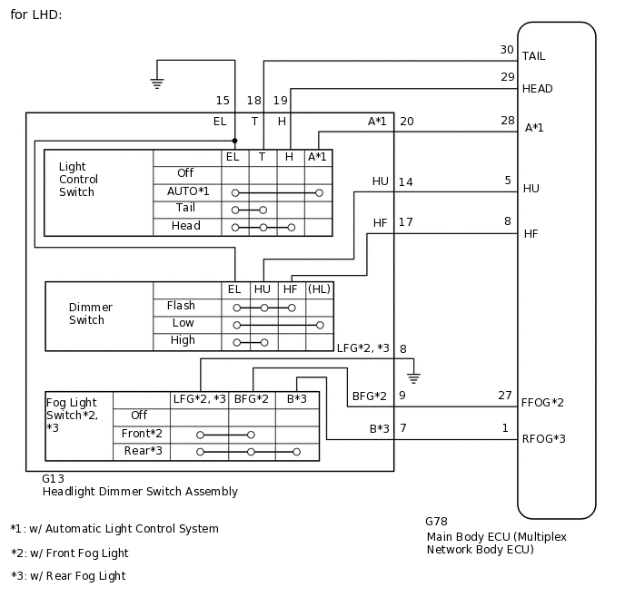
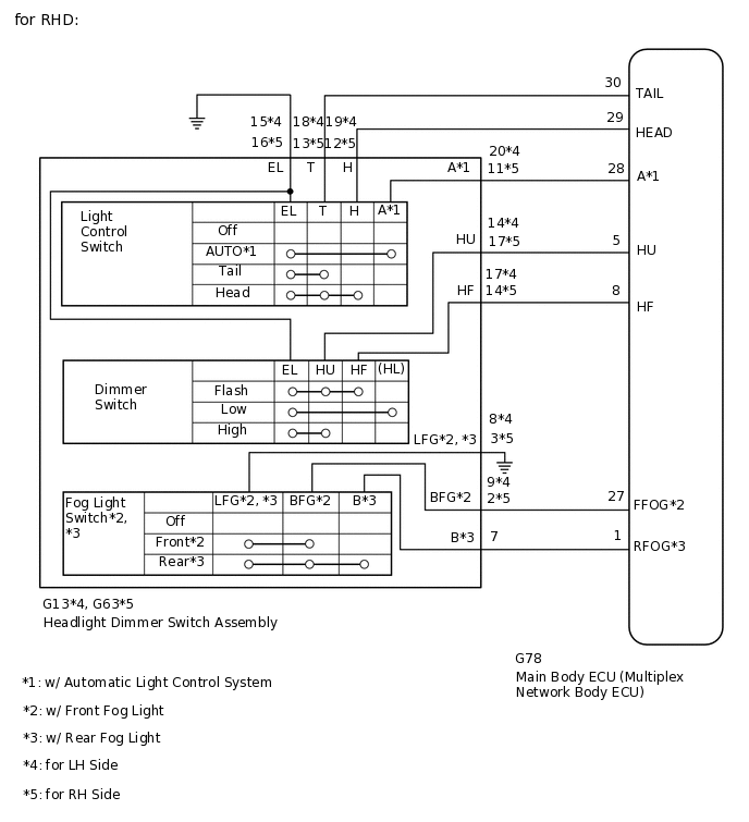
WIRING DIAGRAM
CAUTION / NOTICE / HINT
When replacing the main body ECU (multiplex network body ECU), make sure to replace it with a new one.
PROCEDURE
READ VALUE USING GTS (HEADLIGHT DIMMER SWITCH)
Using the GTS, read the Data List.
Body Electrical > Main Body > Data List
Tester Display
Measurement Item
Range
Normal Condition
Diagnostic Note
Dimmer SW
Headlight dimmer switch high position signal
ON or OFF
ON: Headlight dimmer switch in high or high flash position
OFF: Headlight dimmer switch in low position
-
Passing Light SW
Headlight dimmer switch high flash position (pass) signal
ON or OFF
ON: Headlight dimmer switch in high flash position
OFF: Headlight dimmer switch not in high flash position
-
Rear Fog Light SW
Rear fog light switch signal
ON or OFF
ON: Rear fog light switch on
OFF: Rear fog light switch off
w/ Rear Fog Light
Front Fog Light SW
Front fog light switch signal
ON or OFF
ON: Front fog light switch on
OFF: Front fog light switch off
w/ Front Fog Light
Auto Light SW
Headlight dimmer switch AUTO position signal
ON or OFF
ON: Headlight dimmer switch in AUTO position
OFF: Headlight dimmer switch not in AUTO position
w/ Automatic Light Control System
Head Light SW (Head)
Headlight dimmer switch head position signal
ON or OFF
ON: Headlight dimmer switch in head position
OFF: Headlight dimmer switch not in head position
-
Head Light SW (Tail)
Headlight dimmer switch tail position signal / ON or OFF
ON or OFF
ON: Headlight dimmer switch in tail or head position
OFF: Headlight dimmer switch in neither tail nor head position
-
Body Electrical > Main Body > Data List
Tester Display
Dimmer SW
Passing Light SW
Rear Fog Light SW
Front Fog Light SW
Auto Light SW
Head Light SW (Head)
Head Light SW (Tail)
OK
The display is as specified in the normal condition column.
Result
Proceed to
OK
NG
INSPECT HEADLIGHT DIMMER SWITCH ASSEMBLY (LIGHT CONTROL SWITCH, DIMMER SWITCH FOG LIGHT SWITCH)
Remove the headlight dimmer switch assembly.
w/o Side Marker Light:
w/ Side Marker Light:
Inspect the headlight dimmer switch assembly.
w/o Side Marker Light:
w/ Side Marker Light:
Result
Proceed to
OK
NG
NG REPLACE HEADLIGHT DIMMER SWITCH ASSEMBLY
CHECK HARNESS AND CONNECTOR (HEADLIGHT DIMMER SWITCH ASSEMBLY - MAIN BODY ECU AND BODY GROUND)
for LHD:
Disconnect the G13 headlight dimmer switch assembly connector.
for RHD:
Disconnect the G13*1 or G63*2 headlight dimmer switch assembly connector.
*1: for LH Side
*2: for RH Side
Disconnect the G78 main body ECU (multiplex network body ECU) connector.
Measure the resistance according to the value(s) in the table below.
Standard Resistance
for LHD
Tester Connection
Condition
Specified Condition
G78-27 (FFOG) - G13-9 (BFG)*1
Always
Below 1 Ω
G78-1 (RFOG) - G13-7 (B)*2
G78-5 (HU) - G13-14 (HU)
G78-8 (HF) - G13-17 (HF)
G78-30 (TAIL) - G13-18 (T)
G78-29 (HEAD) - G13-19 (H)
G78-28 (A) - G13-20 (A)*3
G13-8 (LFG) - Body ground*1, *2
G13-15 (EL) - Body ground
G78-27 (FFOG) - Body ground*1
Always
10 kΩ or higher
G78-1 (RFOG) - Body ground*2
G78-5 (HU) - Body ground
G78-8 (HF) - Body ground
G78-30 (TAIL) - Body ground
G78-29 (HEAD) - Body ground
G78-28 (A) - Body ground*3
*1: w/ Front Fog Light
*2: w/ Rear Fog Light
*3: w/ Automatic Light Control System
for RHD
Tester Connection
Condition
Specified Condition
G78-27 (FFOG) - G13-9 (BFG)*1, *4
Always
Below 1 Ω
G78-27 (FFOG) - G63-2 (BFG)*1, *5
G78-1 (RFOG) - G13-7 (B)*2, *4
G78-5 (HU) - G13-14 (HU)*4
G78-5 (HU) - G63-17 (HU)*5
G78-8 (HF) - G13-17 (HF)*4
G78-8 (HF) - G63-14 (HF)*5
G78-30 (TAIL) - G13-18 (T)*4
G78-30 (TAIL) - G63-13 (T)*5
G78-29 (HEAD) - G13-19 (H)*4
G78-29 (HEAD) - G63-12 (H)*5
G78-28 (A) - G13-20 (A)*3, *4
G78-28 (A) - G63-11 (A)*3, *5
G13-8 (LFG) - Body ground*1, *2, *4
G63-3 (LFG) - Body ground*1, *2, *5
G13-15 (EL) - Body ground*4
G63-16 (EL) - Body ground*5
G78-27 (FFOG) - Body ground*1
Always
10 kΩ or higher
G78-1 (RFOG) - Body ground*2
G78-5 (HU) - Body ground
G78-8 (HF) - Body ground
G78-30 (TAIL) - Body ground
G78-29 (HEAD) - Body ground
G78-28 (A) - Body ground*3
*1: w/ Front Fog Light
*2: w/ Rear Fog Light
*3: w/ Automatic Light Control System
*4: for LH Side
*5: for RH Side
Result
Proceed to
OK
NG
NG REPAIR OR REPLACE HARNESS OR CONNECTOR