WIPER AND WASHER SYSTEM Wiper and Washer Switch Circuit
| DTC Code | DTC Name |
|---|---|
| Wiper and Washer Switch Circuit |
DESCRIPTION
This circuit detects the state of the windshield wiper switch assembly (front wiper switch and front washer switch) and sends it to the windshield wiper relay assembly.
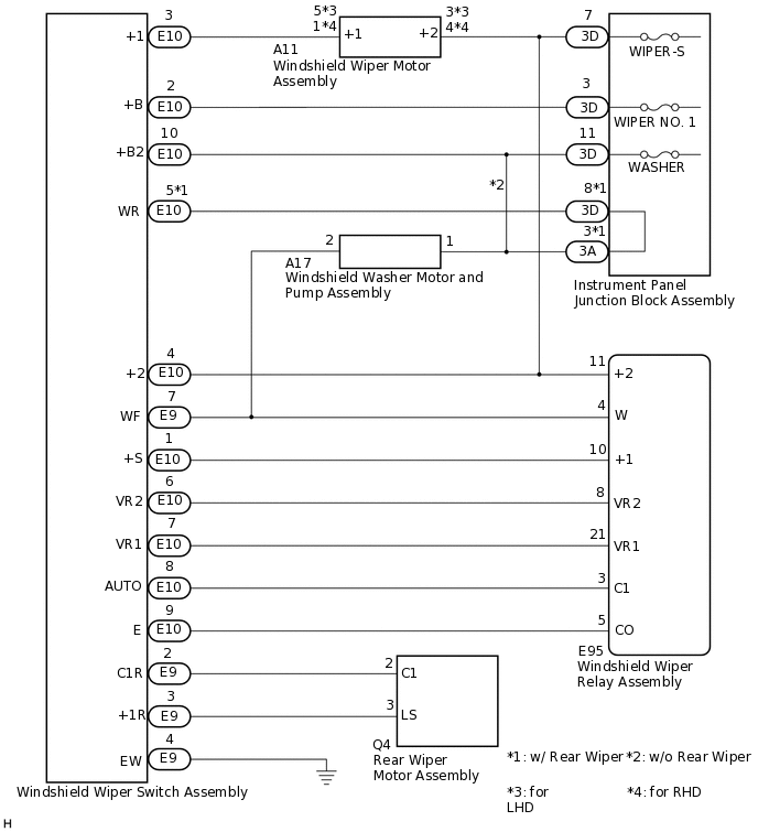
WIRING DIAGRAM
CAUTION / NOTICE / HINT
Inspect the fuses for circuits related to this system before performing the following inspection procedure.
PROCEDURE
INSPECT WINDSHIELD WIPER SWITCH ASSEMBLY
-
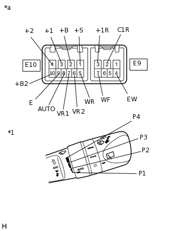
*1
Windshield Wiper Switch Assembly (Adjusting Ring Position)
*a
Component without harness connected
(Windshield Wiper Switch Assembly)
Remove the windshield wiper switch assembly.
Measure the resistance according to the value(s) in the table below.
Standard Resistance
Table 1. Front Wiper Switch Tester Connection
Condition
Specified Condition
E10-2 (+B) - E10-3 (+1)
MIST
Below 1 Ω
E10-3 (+1) - E10-1 (+S)
OFF
E10-3 (+1) - E10-1 (+S)
AUTO
E10-8 (AUTO) - E10-9 (E)
E10-2 (+B) - E10-3 (+1)
LO
E10-2 (+B) - E10-4 (+2)
HI
Table 2. Rear Wiper Switch (w/ Rear Wiper) Tester Connection
Condition
Specified Condition
E9-2 (C1R) - E9-4 (EW)
OFF
10 kΩ or higher
E9-3 (+1R) - E9-4 (EW)
E9-2 (C1R) - E9-4 (EW)
INT
Below 1 Ω
E9-3 (+1R) - E9-4 (EW)
ON
Table 3. Front Washer Switch Tester Connection
Condition
Specified Condition
E9-4 (EW) - E9-7 (WF)
ON
Below 1 Ω
E10-5 (WR) - E10-10 (+B2)
E9-4 (EW) - E9-7 (WF)
OFF
10 kΩ or higher
E10-5 (WR) - E10-10 (+B2)
Table 4. Rear Washer Switch (w/ Rear Wiper) Tester Connection
Condition
Specified Condition
E9-4 (EW) - E10-5 (WR)
ON
Below 1 Ω
E9-7 (WF) - E10-10 (+B2)
E9-4 (EW) - E10-5 (WR)
OFF
10 kΩ or higher
E9-7 (WF) - E10-10 (+B2)
Table 5. Adjusting Ring* Tester Connection
Condition
Specified Condition
E10-6 (VR2) - E10-7 (VR1)
P1
209 to 231 Ω
P2
114 to 126 Ω
P3
58.9 to 65.1 Ω
P4
Below 1 Ω
Tip:*: The rain sensor sensitivity can be adjusted by the windshield wiper switch assembly adjusting ring.
Result
Proceed to
OK
NG
-
CHECK HARNESS AND CONNECTOR (WINDSHIELD WIPER SWITCH ASSEMBLY - WINDSHIELD WIPER RELAY ASSEMBLY AND BODY GROUND)
Disconnect the E95 windshield wiper relay assembly connector.
Disconnect the A11 windshield wiper motor assembly connector.
Disconnect the A17 windshield washer motor and pump assembly connector.
Disconnect the 3D instrument panel junction block assembly connectors.
Measure the resistance according to the value(s) in the table below.
Standard Resistance
Tester Connection
Condition
Specified Condition
E9-4 (EW) - Body ground
Always
Below 1 Ω
E9-7 (WF) - E95-4 (W) - A17-2
Always
Below 1 Ω
E9-7 (WF) - Body ground
Always
10 kΩ or higher
E10-1 (+S) - E95-10 (+1)
Always
Below 1 Ω
E10-1 (+S) - Body ground
Always
10 kΩ or higher
E10-2 (+B) - 3D-3
Always
Below 1 Ω
E10-2 (+B) - Body ground
Always
10 kΩ or higher
E10-3 (+1) - A11-5 (+1)
*1
Always
Below 1 Ω
E10-3 (+1) - A11-1 (+1)
*2
Always
Below 1 Ω
E10-3 (+1) - Body ground
Always
10 kΩ or higher
E10-4 (+2) - E95-11 (+2) - A11-3 (+2) - 3D-7
*1
Always
Below 1 Ω
E10-4 (+2) - E95-11 (+2) - A11-4 (+2) - 3D-7
*2
Always
Below 1 Ω
E10-4 (+2) - Body ground
Always
10 kΩ or higher
E10-6 (VR2) - E95-8 (VR2)
Always
Below 1 Ω
E10-6 (VR2) - Body ground
Always
10 kΩ or higher
E10-7 (VR1) - E95-21 (VR1)
Always
Below 1 Ω
E10-7 (VR1) - Body ground
Always
10 kΩ or higher
E10-8 (AUTO) - E95-3 (C1)
Always
Below 1 Ω
E10-8 (AUTO) - Body ground
Always
10 kΩ or higher
E10-9 (E) - E95-5 (CO)
Always
Below 1 Ω
E10-9 (E) - Body ground
Always
10 kΩ or higher
*1: for LHD
*2: for RHD
Result
Proceed to
OK
NG
NG REPAIR OR REPLACE HARNESS OR CONNECTOR