FRONT SUSPENSION MEMBER INSTALLATION
PROCEDURE
INSTALL FRONT SUSPENSION MEMBER DYNAMIC DAMPER (w/ Dynamic Damper)
Install the front suspension member dynamic damper to the front suspension crossmember sub-assembly with the 2 bolts.
17.5 N*m
178 kgf*cm
13 ft.*lbf
INSTALL ENGINE MOVING CONTROL ROD
Install the engine moving control rod to the front suspension crossmember sub-assembly with the bolt.
110 N*m
1122 kgf*cm
81 ft.*lbf
TEMPORARILY INSTALL FRONT LOWER NO. 1 SUSPENSION ARM SUB-ASSEMBLY LH
Temporarily install the front lower No. 1 suspension arm sub-assembly LH to the front suspension crossmember sub-assembly with the bolt.
TEMPORARILY INSTALL FRONT LOWER NO. 1 SUSPENSION ARM SUB-ASSEMBLY RH
Tip:Perform the same procedure as for the LH side.
INSTALL FRONT STABILIZER BAR
INSTALL STEERING LINK ASSEMBLY
INSTALL FRONT SUSPENSION CROSSMEMBER SUB-ASSEMBLY
Slowly jack up the front suspension crossmember sub-assembly with an engine lifter using 4 attachments or equivalent tools.
CAUTION:The front suspension crossmember sub-assembly is a heavy component. Make sure that it is supported securely.
Make sure to secure the front suspension crossmember sub-assembly to prevent it from dropping.
Note:Use the attachments to keep the front suspension crossmember sub-assembly level.
Temporarily install the front suspension crossmember sub-assembly to the body with the 6 bolts.
Tighten the 2 bolts (A) and 2 bolts (C) on the left and right sides while alternately inserting SST into the left and right side reference holes in the front suspension crossmember sub-assembly.
09670-00011
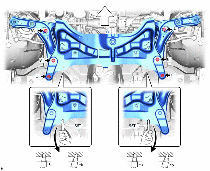
*a
Correct
*b
Incorrect

Front of the Vehicle
-
-
Bolt (A)
85 N*m
867 kgf*cm
63 ft.*lbf
Bolt (C)
48 N*m
489 kgf*cm
35 ft.*lbf
Note:Do not tighten the bolt (B) to the specified torque. Bolt (B) will be fully tightened after the suspension is stabilized.
Lower the engine lifter.
Connect the engine moving control rod with the bolt.
120 N*m
1224 kgf*cm
89 ft.*lbf
CONNECT FRONT LOWER NO. 1 SUSPENSION ARM SUB-ASSEMBLY LH
CONNECT FRONT LOWER NO. 1 SUSPENSION ARM SUB-ASSEMBLY RH
Tip:Perform the same procedure as for the LH side.
INSTALL FRONT STABILIZER BOLT (for LH Side)
INSTALL FRONT STABILIZER BOLT (for RH Side)
Tip:Perform the same procedure as for the LH side.
CONNECT TIE ROD END SUB-ASSEMBLY LH
CONNECT TIE ROD END SUB-ASSEMBLY RH
Tip:Perform the same procedure as for the LH side.
INSTALL EXHAUST PIPE ASSEMBLY
CONNECT NO. 1 STEERING COLUMN HOLE COVER SUB-ASSEMBLY
CONNECT NO. 2 STEERING INTERMEDIATE SHAFT ASSEMBLY
INSTALL STEERING COLUMN HOLE COVER PLATE
INSTALL FRONT WHEELS
STABILIZE SUSPENSION
FULLY TIGHTEN FRONT LOWER NO. 1 SUSPENSION ARM SUB-ASSEMBLY LH
FULLY TIGHTEN FRONT LOWER NO. 1 SUSPENSION ARM SUB-ASSEMBLY RH
Tip:Perform the same procedure as for the LH side.
INSPECT AND ADJUST FRONT WHEEL ALIGNMENT