ENGINE ASSEMBLY INSTALLATION
CAUTION / NOTICE / HINT
for Manual Transaxle:
When the manual transaxle is removed, be sure to use a new clutch release with bearing cylinder assembly and new installation bolts. Removal of the manual transaxle allows the compressed clutch release with bearing cylinder assembly to return to its original position, and dust could damage the seal of the clutch release with bearing cylinder assembly, possibly causing clutch fluid leaks.
PROCEDURE
INSTALL ENGINE HANGER
REMOVE ENGINE FROM ENGINE STAND
Using a chain block and engine sling device, secure the engine assembly.
Note:Adjust the angle of the sling device carefully to prevent the engine assembly or engine hangers from deforming or becoming damaged.
Servicing an engine assembly while it is hanging is dangerous. This can be done only when installing/removing the engine assembly to/from an engine stand.
Remove the engine assembly from the engine stand.
INSTALL DRIVE PLATE AND RING GEAR SUB-ASSEMBLY (for CVT)
Gently place the engine assembly on wooden blocks or equivalent.
CAUTION:This step should be done while hanging the engine assembly using the engine hangers and a chain block.
Install the drive plate and ring gear sub-assembly.
INSTALL CONTINUOUSLY VARIABLE TRANSAXLE ASSEMBLY (for CVT)
INSTALL FLYWHEEL SUB-ASSEMBLY (for Manual Transaxle)
INSTALL CLUTCH DISC ASSEMBLY (for Manual Transaxle)
INSTALL CLUTCH COVER ASSEMBLY (for Manual Transaxle)
INSPECT AND ADJUST CLUTCH COVER ASSEMBLY (for Manual Transaxle)
INSTALL CLUTCH RELEASE WITH BEARING CYLINDER ASSEMBLY (for Manual Transaxle)
REMOVE CLUTCH RELEASE BLEEDER SUB-ASSEMBLY (for Manual Transaxle)
INSPECT CLUTCH PIPE LINE (for Manual Transaxle)
INSTALL CLUTCH RELEASE BLEEDER SUB-ASSEMBLY (for Manual Transaxle)
INSTALL BLEEDER CLUTCH RELEASE TUBE (for Manual Transaxle)
INSTALL MANUAL TRANSAXLE ASSEMBLY (for Manual Transaxle)
INSTALL STARTER ASSEMBLY
INSTALL FLYWHEEL HOUSING SIDE COVER
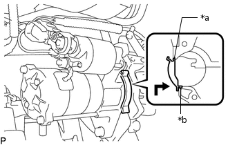
*a
Protruding Portion
*b
Claw
Insert the protruding portion into the end of the cylinder block sub-assembly and while pushing it along the cylinder block sub-assembly, fit the claw into the stiffening crankcase assembly.
Note:Make sure that the claw makes a click sound, indicating that it fits tightly.
Replace the flywheel housing side cover with a new one if the claw does not fit tightly or is deformed.
INSTALL ENGINE WIRE
Install the engine wire to the engine assembly with transaxle.
CONNECT NO. 5 WATER BY-PASS HOSE (for CVT)
Connect the No. 5 water by-pass hose to the No. 1 water by-pass pipe.
REMOVE ENGINE HANGER
Remove the 2 bolts and No. 1 and No. 2 engine hangers.
INSTALL WIRE HARNESS CLAMP BRACKET
Install the wire harness clamp bracket with the bolt.
39 N*m
398 kgf*cm
29 ft.*lbf
Connect the clamp and wire harness to the wire harness clamp bracket.
INSTALL ENGINE MOUNTING INSULATOR SUB-ASSEMBLY RH
Tip:Perform this procedure only when replacement of the engine mounting insulator sub-assembly RH is necessary.
Install the engine mounting insulator sub-assembly RH with the 3 bolts.
95 N*m
969 kgf*cm
70 ft.*lbf
Install the cooler pipe clamp bracket to the engine mounting insulator sub-assembly RH with the bolt.
9.8 N*m
100 kgf*cm
87 in.*lbf
Connect the cooler pipe clamp to the engine mounting insulator sub-assembly RH.
Install the radiator reservoir tank with the 2 bolts.
5.0 N*m
51 kgf*cm
44 in.*lbf
INSTALL ENGINE MOUNTING INSULATOR LH
Tip:Perform this procedure only when replacement of the engine mounting insulator LH is necessary.
Install the engine mounting insulator LH with the 4 bolts.
95 N*m
969 kgf*cm
70 ft.*lbf
TEMPORARILY TIGHTEN REAR ENGINE MOUNTING INSULATOR
Tip:Perform this procedure only when replacement of the rear engine mounting insulator is necessary.
Temporarily install the rear engine mounting insulator to the rear engine mounting bracket with the through bolt.
TEMPORARILY TIGHTEN FRONT ENGINE MOUNTING INSULATOR
Tip:Perform this procedure only when replacement of the front engine mounting insulator is necessary.
Temporarily install the front engine mounting insulator to the front engine mounting bracket with the through bolt and nut.
INSTALL ENGINE ASSEMBLY WITH TRANSAXLE
Set the engine assembly with transaxle on an engine lifter.
Note:Place height adjustment attachments and plate lift attachments under the engine assembly with transaxle.
Operate the engine lifter and lift the engine assembly with transaxle to the position where the engine mounting insulator sub-assembly RH and engine mounting insulator LH can be installed.
CAUTION:Do not raise the engine assembly with transaxle more than necessary. If the engine assembly with transaxle is raised excessively, the vehicle may also be lifted up.
Note:Make sure that the engine assembly with transaxle is clear of all wiring and hoses.
While raising the engine assembly with transaxle into the vehicle, do not allow it to contact the vehicle.
Install the engine mounting insulator LH with the through bolt and nut.
56 N*m
571 kgf*cm
41 ft.*lbf
Tip:Tighten the through bolt while holding the nut.
-
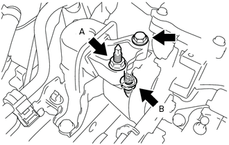
Install the engine mounting insulator sub-assembly RH with the bolt and 2 nuts.
Nut A
95 N*m
969 kgf*cm
70 ft.*lbf
Nut B
52 N*m
530 kgf*cm
38 ft.*lbf
Bolt
95 N*m
969 kgf*cm
70 ft.*lbf
Install the front crossmember sub-assembly with the 4 bolts.
99 N*m
1010 kgf*cm
73 ft.*lbf
Connect the front engine mounting insulator sub-assembly to the front crossmember sub-assembly with the 2 bolts.
95 N*m
969 kgf*cm
70 ft.*lbf
INSTALL FRONT SUSPENSION CROSSMEMBER SUB-ASSEMBLY
INSTALL FRONT SUSPENSION MEMBER REAR BRACE LH
INSTALL FRONT SUSPENSION MEMBER REAR BRACE RH
Tip:Perform the same procedure as for the LH side.
INSTALL FRONT SUSPENSION MEMBER REINFORCEMENT LH
INSTALL FRONT SUSPENSION MEMBER REINFORCEMENT RH
INSTALL FRONT ENGINE MOUNTING BRACKET LOWER REINFORCEMENT
FULLY INSTALL REAR ENGINE MOUNTING INSULATOR
Fully install the rear engine mounting insulator with the through bolt.
95 N*m
969 kgf*cm
70 ft.*lbf
FULLY INSTALL FRONT ENGINE MOUNTING INSULATOR
Fully install the front engine mounting insulator with the nut and through bolt.
85 N*m
867 kgf*cm
63 ft.*lbf
Tip:Tighten the through bolt while holding the nut.
INSTALL DRIVE PLATE AND TORQUE CONVERTER ASSEMBLY SETTING BOLT (for CVT)
INSTALL FLYWHEEL HOUSING UNDER COVER
Install the flywheel housing under cover.
INSTALL DRIVE SHAFT ASSEMBLY
INSTALL FRONT EXHAUST PIPE ASSEMBLY
CONNECT NO. 1 STEERING COLUMN HOLE COVER SUB-ASSEMBLY
CONNECT NO. 2 STEERING INTERMEDIATE SHAFT ASSEMBLY
INSTALL COLUMN HOLE COVER SILENCER SHEET
CONNECT WIRE HARNESS
for CVT:
Install the No. 3 engine wire to the CVT with the bolt and clamp.
12.5 N*m
127 kgf*cm
9 ft.*lbf
for Manual Transaxle:
Install the No. 3 engine wire to the manual transaxle with the bolt.
12.5 N*m
127 kgf*cm
9 ft.*lbf
Connect the 3 wire harness connectors and wire harness to the engine room junction block and engage the 2 claws.
Install the 2 nuts to the engine room relay block and junction block assembly.
8.5 N*m
87 kgf*cm
75 in.*lbf
Install the No. 1 engine room relay block cover to the engine room relay block and junction block assembly.
Connect the wire harness clamp.
Connect the ECM connector and lower the lever.
INSTALL COMPRESSOR ASSEMBLY WITH PULLEY
CONNECT SUCTION HOSE SUB-ASSEMBLY
CONNECT DISCHARGE HOSE SUB-ASSEMBLY
INSTALL GENERATOR ASSEMBLY (for 90A Type)
INSTALL GENERATOR ASSEMBLY (for 100A Type)
INSTALL V-RIBBED BELT
ADJUST V-RIBBED BELT
INSPECT V-RIBBED BELT
CONNECT FUEL TUBE SUB-ASSEMBLY
Connect the fuel tube connector and fuel pipe.
Note:Align the fuel tube connector with the fuel pipe, then push the fuel tube connector in until the retainer makes a "click" sound.
If the connection is tight, apply a small amount of engine oil to the tip of the fuel pipe.
After connecting, pull the fuel pipe and fuel tube connector to make sure that they are securely connected.
Engage the claw and install the No. 1 fuel pipe clamp.
CONNECT INLET HEATER WATER HOSE
Connect the inlet heater water hose to the air conditioner unit assembly and slide the clip to secure it.
CONNECT OUTLET HEATER WATER HOSE (for Manual Transaxle)
Connect the outlet heater water hose to the No. 1 water by-pass pipe and slide the clip to secure it.
CONNECT OUTLET HEATER WATER HOSE (for CVT)
Connect the outlet heater water hose to the No. 1 water by-pass pipe and slide the clip to secure it.
Connect the outlet heater water hose to the air conditioner unit assembly and slide the clip to secure it.
CONNECT UNION TO VACUUM TUBE HOSE
Connect the union to vacuum tube hose to the air tube and slide the clip to secure it.
INSTALL NO. 1 FUEL VAPOR FEED HOSE
Connect the No. 1 fuel vapor feed hose to the vacuum switching valve assembly and slide the clip to secure it.
CONNECT CLUTCH HOSE (for Manual Transaxle)
Connect the clutch hose and install a new clip to the clutch hose.
Note:Install the clip as far as it will go.
Using a 10 mm union nut wrench, connect the bleeder clutch release tube to the clutch hose while holding the clutch hose.
15.2 N*m
155 kgf*cm
11 ft.*lbf
Note:Use the formula to calculate special torque values for situations where a union nut wrench is combined with a torque wrench.
This torque value is effective when the union nut wrench is parallel to the torque wrench.
Do not kink or damage the clutch hose.
Do not allow any foreign matter such as dirt or dust to enter the clutch hose from the clip or bracket.
BLEED CLUTCH LINE (for Manual Transaxle)
CONNECT TRANSMISSION CONTROL CABLE ASSEMBLY (for Manual Transaxle)
Connect the transmission control cable assembly to the rear engine mounting bracket with the bolt.
5.0 N*m
51 kgf*cm
44 in.*lbf
-
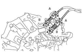
Install the 2 transmission control cable assemblies to the control cable bracket with 2 new clips (A).
Install the 2 transmission control cable assemblies to the manual transaxle assembly with the 2 clips (B).
CONNECT TRANSMISSION CONTROL CABLE ASSEMBLY (for CVT)
Connect the transmission control cable assembly to the rear engine mounting insulator with the bolt.
5.0 N*m
51 kgf*cm
44 in.*lbf
Install the transmission control cable assembly to the transmission control cable bracket with a new clip.
-
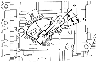
*a
P Position
*b
N Position
Turn the lever clockwise until it stops, then turn it counterclockwise 2 notches.
Install the transmission control cable assembly to the control shaft lever with the nut.
12 N*m
122 kgf*cm
9 ft.*lbf
CONNECT NO. 2 RADIATOR HOSE
Connect the No. 2 radiator hose to the water inlet and slide the clip to secure it.
CONNECT NO. 1 RADIATOR HOSE (for Manual Transaxle)
Connect the No. 1 radiator hose to the cylinder head sub-assembly and slide the clip to secure it.
CONNECT NO. 1 RADIATOR HOSE (for CVT)
Connect the No. 1 radiator hose to the cylinder head sub-assembly and slide the clip to secure it.
Connect breather plug hose to the clamp.
INSTALL BATTERY CARRIER ASSEMBLY
Install the battery carrier assembly with the 4 bolts.
18.5 N*m
189 kgf*cm
14 ft.*lbf
Connect the radiator pipe with the 2 bolts.
18.5 N*m
189 kgf*cm
14 ft.*lbf
Connect the 2 wire harness clamps.
INSTALL BATTERY
Install the battery tray.
Install the battery.
-
*a
Bolt
*b
Nut
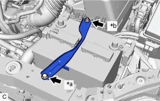
Install the battery clamp sub-assembly with the bolt and nut.
Bolt
16.5 N*m
168 kgf*cm
12 ft.*lbf
Nut
3.5 N*m
36 kgf*cm
31 in.*lbf
Connect the cable to the positive (+) battery terminal.
5.4 N*m
55 kgf*cm
48 in.*lbf
INSTALL AIR CLEANER CASE SUB-ASSEMBLY
Install the air cleaner case sub-assembly with the 3 bolts.
7.0 N*m
71 kgf*cm
62 in.*lbf
Install the wire harness clamp to the air cleaner case.
Install the air cleaner filter element sub-assembly.
INSTALL AIR CLEANER CAP SUB-ASSEMBLY
CONNECT CABLE TO NEGATIVE BATTERY TERMINAL
Connect the cable to the negative (-) battery terminal.
5.4 N*m
55 kgf*cm
48 in.*lbf
Note:When disconnecting the cable, some systems need to be initialized after the cable is reconnected.
ADD ENGINE OIL
ADD MANUAL TRANSAXLE OIL (for Manual Transaxle)
ADD ENGINE COOLANT
ADD CONTINUOUSLY VARIABLE TRANSAXLE FLUID (for CVT)
INSPECT ENGINE OIL LEVEL
ADJUST SHIFT LEVER POSITION (for Manual Transaxle)
INSPECT SHIFT LEVER POSITION (for CVT)
ADJUST SHIFT LEVER POSITION (for CVT)
INSPECT FOR FUEL LEAK
INSPECT FOR COOLANT LEAK
INSPECT FOR OIL LEAK
INSPECT FOR EXHAUST GAS LEAK
INSTALL REAR ENGINE UNDER COVER LH
Install the rear engine under cover LH with the 5 clips.
INSTALL REAR ENGINE UNDER COVER RH
Install the rear engine under cover RH with the 5 clips.
INSTALL NO. 2 ENGINE UNDER COVER
Install the No. 2 engine under cover with the 5 clips.
INSTALL NO. 1 ENGINE UNDER COVER (for Half Cover Type)
Install the No. 1 engine under cover with the 7 clips and 2 bolts.
INSTALL NO. 1 ENGINE UNDER COVER (for Metal Type)
Install the No. 1 engine under cover with the 2 clips and 5 bolts.
INSTALL FRONT LOWER BUMPER ABSORBER
Install the front lower bumper absorber with the 4 screws and 8 bolts.
CHARGE AIR CONDITIONING SYSTEM WITH REFRIGERANT
WARM UP ENGINE
INSPECT FOR REFRIGERANT LEAK
INSTALL FRONT WHEELS
103 N*m
1050 kgf*cm
76 ft.*lbf
INSPECT IGNITION TIMING
INSPECT ENGINE IDLE SPEED
INSPECT CO/HC
ADJUST FRONT WHEEL ALIGNMENT
INSTALL NO. 2 CYLINDER HEAD COVER
Engage the 4 clips to install the No. 2 cylinder head cover.
Note:Be sure to engage the clips securely.
Do not apply excessive force or hit the No. 2 cylinder head cover to engage the clips. This may cause the No. 2 cylinder head cover to break.
INSPECT FOR SPEED SENSOR SIGNAL