CYLINDER HEAD REPLACEMENT
-
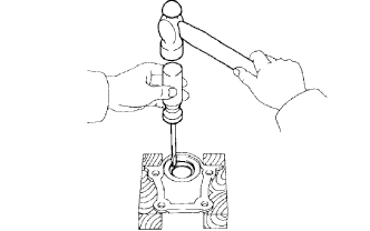
REMOVE NO. 2 OIL SEAL RETAINER OIL SEAL
-
Using a screwdriver and hammer, tap out the oil seal.
Note
Tape the screwdriver tip.
-
-
REMOVE INTAKE VALVE GUIDE BUSH
-
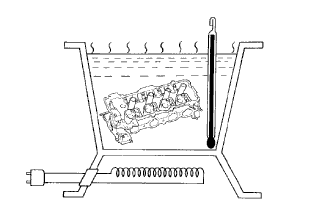
Gradually heat the cylinder head to approximately 80 to 100°C (176 to 212°F).
-
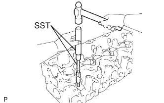
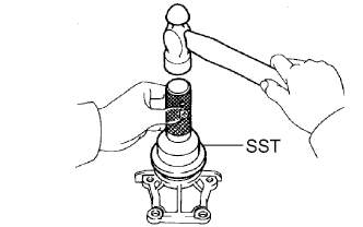
Using SST and a hammer, tap out the valve guide bushing.
- SST
- 09201-10000 ( 09201-01080 )
- 09950-70010 ( 09951-07100 )
-
-
REMOVE EXHAUST VALVE GUIDE BUSH
-
Gradually heat the cylinder head to approximately 80 to 100°C (176 to 212°F).
-
Using SST and a hammer, tap out the valve guide bushing.
- SST
- 09201-10000 ( 09201-01080 )
- 09950-70010 ( 09951-07100 )
-
-
INSTALL INTAKE VALVE GUIDE BUSH
-
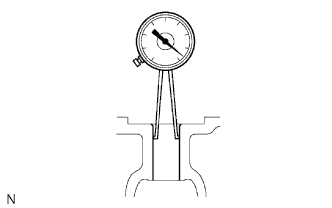
Using a caliper gauge, measure the bush bore diameter of the cylinder head.
Select a new guide bush (STD or O/S 0.05) Bush Size Bush Bore Diameter Use STD 13.004 to 13.025 mm (0.5120 to 0.5128 in.) Use O/S 0.05 13.054 to 13.075 mm (0.5139 to 0.5148 in.) If the bush bore diameter of the cylinder head is greater than 13.025 mm (0.5128 in.), machine the bush bore to dimension of 13.054 to 13.075 mm (0.5139 to 0.5148 in.).
If the bush bore diameter of the cylinder head is greater than 13.075 mm (0.5148 in.), replace the cylinder head.
-
Gradually heat the cylinder head to approximately 80 to 100°C (176 to 212°F).
-
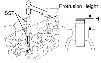
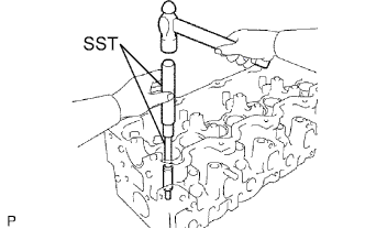
Using SST and a hammer, tap in a new guide bush to the specified protrusion height.
- SST
- 09201-10000 ( 09201-01080 )
- 09950-70010 ( 09951-07100 )
Standard protrusion height (H) 10.8 to 11.2 mm (0.425 to 0.441 in.) -
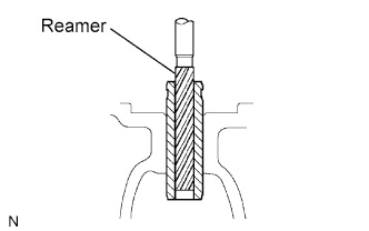
Using a sharp 8.0 mm reamer, ream the guide bush to obtain the standard specified clearance between the guide bush and valve stem.
-
-
INSTALL EXHAUST VALVE GUIDE BUSH
-
Using a caliper gauge, measure the bush bore diameter of the cylinder head.
Select a new guide bush (STD or O/S 0.05) Bush Size Bush Bore Diameter Use STD 13.004 to 13.025 mm (0.5120 to 0.5128 in.) Use O/S 0.05 13.054 to 13.075 mm (0.5139 to 0.5148 in.) If the bush bore diameter of the cylinder head is greater than 13.025 mm (0.5128 in.), machine the bush bore to dimension of 13.054 to 13.075 mm (0.5139 to 0.5148 in.).
If the bush bore diameter of the cylinder head is greater than 13.075 mm (0.5148 in.), replace the cylinder head.
-
Gradually heat the cylinder head to approximately 80 to 100°C (176 to 212°F).
-
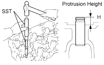
Using SST and a hammer, tap in a new guide bush to the specified protrusion height.
- SST
- 09201-10000 ( 09201-01080 )
- 09950-70010 ( 09951-07100 )
Standard protrusion height (H) 10.8 mm to 11.2 mm (0.425 to 0.441 in.) -
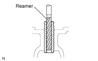
Using a sharp 8.0 mm reamer, ream the guide bush to obtain the standard specified clearance between the guide bush and valve stem.
-
-
INSTALL NO. 2 OIL SEAL RETAINER OIL SEAL
-
Using SST and a hammer, tap in a new oil seal until its surface is flush with the oil seal retainer edge.
- SST
- 09223-46011
-
Apply MP grease to the oil seal lip.
-