SFI SYSTEM, Diagnostic DTC:P0071,P0096,P0097,P0098 and P0099
| DTC Code | DTC Name |
|---|---|
| P0071 | Ambient Air Temperature Sensor Circuit "A" Range / Performance |
| P0096 | Intake Air Temperature Sensor 2 Circuit Range / Performance Bank 1 |
| P0097 | Intake Air Temperature Sensor 2 Circuit Low Bank 1 |
| P0098 | Intake Air Temperature Sensor 2 Circuit High Bank 1 |
| P0099 | Intake Air Temperature Sensor 2 Circuit Intermittent / Erratic Bank 1 |
DESCRIPTION
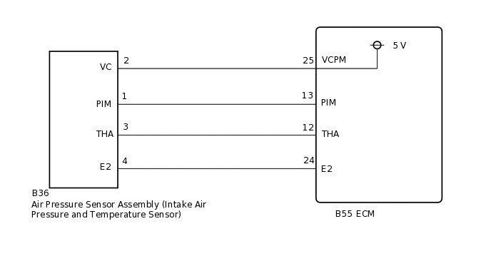
The intake air temperature sensor is built into the air pressure sensor assembly and monitors the intake air temperature. The intake air temperature sensor has a built-in thermistor that varies its resistance depending on the temperature of the intake air. When the air temperature is low, the resistance in the thermistor increases. When the temperature is high, the resistance drops. The variations in resistance are reflected in the voltage applied to the ECM terminal.
DTC No. |
Detection Item |
DTC Detection Condition |
Trouble Area |
MIL |
Memory |
|---|---|---|---|---|---|
P0071 |
Ambient Air Temperature Sensor Circuit "A" Range / Performance |
Difference between the readings of ambient temperature and intake air temperature is outside threshold. |
|
Does not come on |
DTC stored |
P0096 |
Intake Air Temperature Sensor 2 Circuit Range / Performance Bank 1 |
Change in intake air temperature sensor signal is outside threshold. |
|
Comes on |
DTC stored |
P0097 |
Intake Air Temperature Sensor 2 Circuit Low Bank 1 |
Short to ground in intake air temperature sensor circuit. |
|
Comes on |
DTC stored |
P0098 |
Intake Air Temperature Sensor 2 Circuit High Bank 1 |
Open or short to +B in intake air temperature sensor circuit. |
|
Comes on |
DTC stored |
P0099 |
Intake Air Temperature Sensor 2 Circuit Intermittent / Erratic Bank 1 |
Intake air temperature signal is outside threshold. |
|
Comes on |
DTC stored |
MONITOR DESCRIPTION
These DTCs are stored when a malfunction is detected in the intake air temperature sensor circuit. If the difference between the intake air temperature and the ambient temperature is outside of the threshold when the ignition switch is turned to ON after a few hours have elapsed since the engine was stopped, or there is an open or short in the intake air temperature sensor circuit, the ECM will store a DTC.
WIRING DIAGRAM
PROCEDURE
CHECK ANY OTHER DTCS OUTPUT (IN ADDITION TO DTC P0071, P0096, P0097, P0098 AND/OR P0099)
Connect the GTS to the DLC3.
Turn the ignition switch to ON.
Turn the GTS on.
Enter the following menus: Powertrain / Engine / Trouble Codes.
Check for DTCs.
Powertrain > Engine > Trouble Codes
Result
Result
Proceed to
DTC P0071, P0096, P0097, P0098 and/or P0099 is output
A
DTC P0071, P0096, P0097, P0098 and/or P0099 and other DTCs are output
B
Tip:If DTC P0071, P0096, P0097, P0098 and/or P0099 and P0658, P2670 or P2685 are output simultaneously, troubleshoot for DTC P0658, P2670 or P2685 first.
CHECK TERMINAL VOLTAGE (POWER SOURCE OF AIR PRESSURE SENSOR ASSEMBLY)
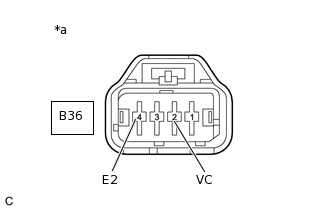
*a
Front view of wire harness connector
(to Air Pressure Sensor Assembly)
Disconnect the air pressure sensor assembly connector.
Turn the ignition switch to ON.
Measure the voltage according to the value(s) in the table below.
Standard Voltage
Tester Connection
Condition
Specified Condition
B36-2 (VC) - B36-4 (E2)
Ignition switch ON
4.5 to 5.5 V
Result
Proceed to
OK
NG
NG CHECK HARNESS AND CONNECTOR (AIR PRESSURE SENSOR ASSEMBLY - ECM)Click here
CHECK HARNESS AND CONNECTOR (AIR PRESSURE SENSOR ASSEMBLY - ECM)
Disconnect the air pressure sensor assembly connector.
Disconnect the ECM connector.
Measure the resistance according to the value(s) in the table below.
Standard Resistance
Tester Connection
Condition
Specified Condition
B36-3 (THA) - B55-12 (THA)
Always
Below 1 Ω
B36-4 (E2) - B55-24 (E2)
Always
Below 1 Ω
B36-3 (THA) or B55-12 (THA) - Body ground and other terminals
Always
10 kΩ or higher
B36-4 (E2) or B55-24 (E2) - Body ground and other terminals
Always
10 kΩ or higher
Result
Proceed to
OK
NG
NG REPAIR OR REPLACE HARNESS OR CONNECTOR
REPLACE AIR PRESSURE SENSOR ASSEMBLY (INTAKE AIR TEMPERATURE SENSOR)
Replace the air pressure sensor assembly (intake air temperature sensor).
Result
Proceed to
NEXT
CHECK WHETHER DTC OUTPUT RECURS (DTC P0071, P0096, P0097, P0098 AND/OR P0099)
Connect the GTS to the DLC3.
Turn the ignition switch to ON.
Turn the GTS on.
Clear the DTCs.
Powertrain > Engine > Clear DTCs
Turn the ignition switch off and wait for a few minutes.
Perform the drive test.
Turn the GTS on.
Enter the following menus: Powertrain / Engine / Trouble Codes.
Check for DTCs.
Powertrain > Engine > Trouble Codes
Result
Result
Proceed to
DTC P0071, P0096, P0097, P0098 and/or P0099 is output
A
DTCs are not output
B
B END
CHECK HARNESS AND CONNECTOR (AIR PRESSURE SENSOR ASSEMBLY - ECM)
Disconnect the air pressure sensor assembly connector.
Disconnect the ECM connector.
Measure the resistance according to the value(s) in the table below.
Standard Resistance
Tester Connection
Condition
Specified Condition
B36-2 (VC) - B55-25 (VCPM)
Always
Below 1 Ω
B36-2 (VC) or B55-25 (VCPM) - Body ground and other terminals
Always
10 kΩ or higher
Result
Proceed to
OK
NG
NG REPAIR OR REPLACE HARNESS OR CONNECTOR