SFI SYSTEM, Diagnostic DTC:P24522A
| DTC Code | DTC Name |
|---|---|
| P24522A | Particulate Filter Pressure Sensor "A" Signal Stuck In Range |
DESCRIPTION
Refer to DTC P244B00.
DTC No. |
Detection Item |
DTC Detection Condition |
Trouble Area |
MIL |
Memory |
Note |
|---|---|---|---|---|---|---|
P24522A |
Particulate Filter Pressure Sensor "A" Signal Stuck In Range |
When ignition switch to ON, the differential pressure sensor output learning value at atmospheric pressure is above or below the specified value for 1 second or more (1 trip detection logic). |
|
Does not come on |
DTC stored |
SAE Code: P2453 |
MONITOR DESCRIPTION
The differential pressure sensor output learning value is updated when ignition switch off after completely engine warmed up drive cycle. The sensor output should show its neutral (zero) value at the condition. The sensor output stuck in range is judged when the learning value is below or above the specified value at ignition switch to ON after the learning value updated.
MONITOR STRATEGY
Frequency of Operation |
Continuous |
CONFIRMATION DRIVING PATTERN
Connect the GTS to the DLC3.
Turn the ignition switch to ON.
Turn the GTS on.
Clear the DTCs (even if no DTCs are stored, perform the clear DTC procedure).
Turn the ignition switch off and wait for at least 30 seconds.
Start the engine and warm it up until the engine coolant temperature reaches 75°C (167°F) or higher.
Idle the engine for 1 minute or more.
Turn the ignition switch off and wait for at least 30 seconds.
Turn the ignition switch to ON.
Turn the GTS on.
Enter the following menus: Powertrain / Engine / Trouble Codes.
Read the pending DTCs.
Tip:If a pending DTC is output, the system is malfunctioning.
If a pending DTC is not output, perform the following procedure.
Enter the following menus: Powertrain / Engine / Utility / All Readiness.
Input the DTC: P24522A.
Check the DTC judgment result.
GTS Display
Description
NORMAL
DTC judgment completed
System normal
ABNORMAL
DTC judgment completed
System abnormal
INCOMPLETE
DTC judgment not completed
Perform driving pattern after confirming DTC enabling conditions
Tip:If the judgment result is NORMAL, the system is normal.
If the judgment result is ABNORMAL, the system has a malfunction.
WIRING DIAGRAM
Refer to DTC P010012 for the mass air flow meter sub-assembly circuit.
Refer to DTC P244B00 for the differential pressure sensor circuit.
CAUTION / NOTICE / HINT
Read Freeze Frame Data using the GTS. The ECM records vehicle and driving condition information as Freeze Frame Data the moment a DTC is stored. When troubleshooting, Freeze Frame Data can help determine if the vehicle was moving or stationary, if the engine was warmed up or not, if the air fuel ratio was lean or rich, and other data from the time the malfunction occurred.
PROCEDURE
CHECK ANY OTHER DTCS OUTPUT (IN ADDITION TO DTC P24522A)
Connect the GTS to the DLC3.
Turn the ignition switch to ON.
Turn the GTS on.
Enter the following menus: Powertrain / Engine / Trouble Codes.
Read the DTCs.
Powertrain > Engine > Trouble Codes
Result
Result
Proceed to
DTC P24522A is output
A
DTC P24522A and other DTCs are output
B
Tip:If any DTCs other than P24522A are output, troubleshoot those DTCs first.
CHECK FOR EXHAUST GAS LEAK
Check for exhaust gas leaks.
OK
No gas leaks in exhaust system.
Result
Proceed to
OK
NG
NG REPAIR OR REPLACE EXHAUST SYSTEM
CHECK CONNECTION OF VACUUM TRANSMITTING HOSE ASSEMBLY (DIFFERENTIAL PRESSURE SENSOR - VACUUM PIPE)
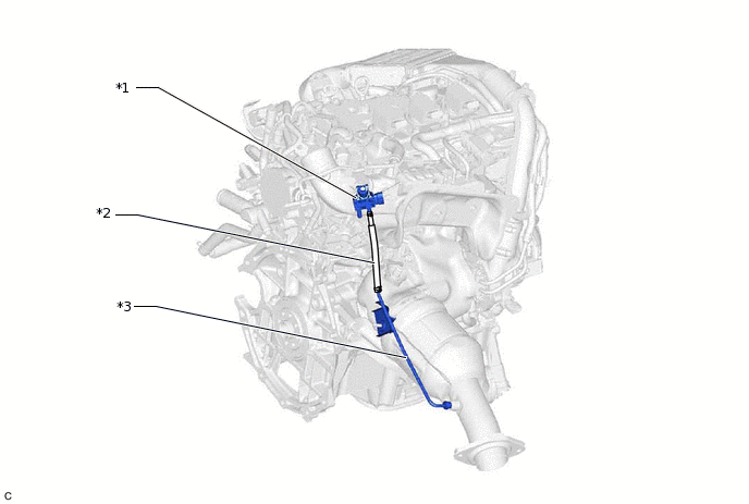
*1
Differential Pressure Sensor
*2
Vacuum Transmitting Hose Assembly
*3
No. 1 Vacuum Pipe
-
-
Check the vacuum transmitting hose assembly is no exhaust gas leak between the differential pressure sensor and the vacuum pipe.
OK
The vacuum transmitting hose assembly is no exhaust gas leak.
Result
Proceed to
OK
NG
NG REPAIR OR REPLACE MALFUNCTIONING PARTS
CHECK BLOCKAGE OF VACUUM TRANSMITTING HOSE ASSEMBLY AND VACUUM PIPE
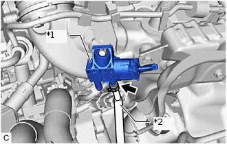
*1
Differential Pressure Sensor
*2
Vacuum Transmitting Hose Assembly
CAUTION:Be careful of being burned by exhaust gases during the following inspection.
Disconnect vacuum transmitting hose assembly on the differential pressure sensor.
Start the engine.
Check if there are exhaust gas pulsations from vacuum transmitting hose assembly during idling.
Result
Proceed to
OK
NG
NG REPAIR OR REPLACE MALFUNCTIONING PARTS
INSPECT DIFFERENTIAL PRESSURE SENSOR
Inspect the differential pressure sensor.
Result
Proceed to
OK
NG
NG CHECK HARNESS AND CONNECTOR (DIFFERENTIAL PRESSURE SENSOR - ECM)Click here
CLEAR DTC
Connect the GTS to the DLC3.
Turn the ignition switch to ON.
Turn the GTS on.
Clear the DTCs.
Powertrain > Engine > Clear DTCs
Turn the ignition switch off and wait for at least 30 seconds.
Result
Proceed to
NEXT
CHECK WHETHER DTC OUTPUT RECURS (DTC P24522A)
Drive the vehicle in accordance with the driving pattern described in Confirmation Driving Pattern.
Enter the following menus: Powertrain / Engine / Trouble Codes.
Read the Pending DTCs.
Powertrain > Engine > Trouble Codes
OK
DTCs are not output
Result
Proceed to
NEXT
NEXT END
CHECK HARNESS AND CONNECTOR (DIFFERENTIAL PRESSURE SENSOR - ECM)
Disconnect the differential pressure sensor connector.
Disconnect the ECM connector.
Measure the resistance according to the value(s) in the table below.
Standard Resistance
Tester Connection
Condition
Specified Condition
B242-3 (VC) - B208-80 (VC)
Always
Below 1 Ω
B242-2 (PEX) - B208-78 (PEX)
Always
Below 1 Ω
B242-1 (E2) - B208-79 (EPEX)
Always
Below 1 Ω
B242-3 (VC) or B208-80 (VC) - Body ground and other terminals
Always
10 kΩ or higher
B242-2 (PEX) or B208-78 (PEX) - Body ground and other terminals
Always
10 kΩ or higher
Result
Proceed to
OK
NG
NG REPAIR OR REPLACE HARNESS OR CONNECTOR
REPLACE DIFFERENTIAL PRESSURE SENSOR
Replace the differential pressure sensor.
Start the engine and allow it to idle until the engine coolant temperature reaches 75°C (167°F) or higher (A).
Turn the ignition switch off and wait for 30 seconds or more (B).
Repeat the above procedures (A) and (B) 3 times.
Tip:Procedures (A) and (B) must be repeated 3 times to complete the differential pressure sensor learning process.
Result
Proceed to
NEXT
NEXT END