AIR CONDITIONING SYSTEM (for Automatic Air Conditioning System) Heater Relay Circuit
DESCRIPTION
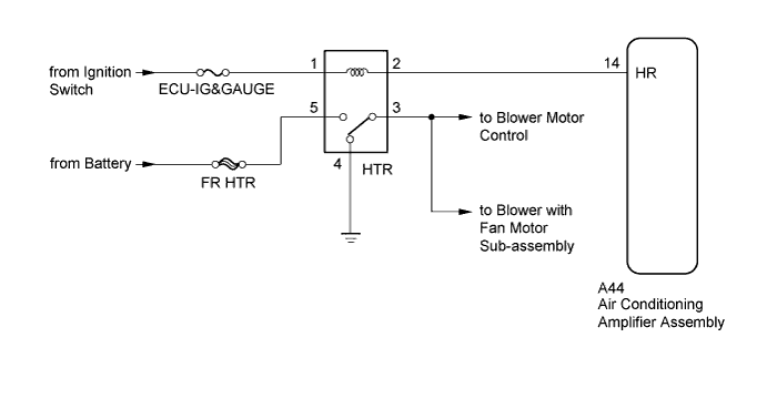
The heater relay is turned on by signals from the air conditioning amplifier assembly. The heater relay supplies power to the blower motor control.
WIRING DIAGRAM
INSPECTION PROCEDURE
Note
Inspect the fuses for circuits related to this system before performing the following inspection procedure.
PROCEDURE
-
INSPECT HEATER RELAY (HTR)
-
Remove the HTR relay from the driver side junction block assembly Click here.
-
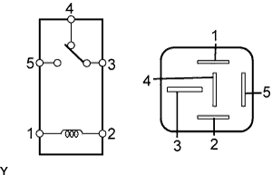
Measure the resistance according to the value(s) in the table below.
Standard Resistance Tester Connection Condition Specified Condition 3 - 4 Battery voltage is not applied to terminals 1 and 2 Below 1 Ω 3 - 5 10 kΩ or higher 3 - 4 Battery voltage is applied to terminals 1 and 2 10 kΩ or higher 3 - 5 Below 1 Ω
NG 
REPLACE HEATER RELAY (HTR) Click here
OK 
-
-
CHECK HARNESS AND CONNECTOR (HTR RELAY - AIR CONDITIONING AMPLIFIER, BATTERY AND BODY GROUND)
-
Remove the HTR relay from the driver side junction block assembly Click here.
-
Disconnect the A44 air conditioning amplifier assembly connector.
-
Measure the resistance according to the value(s) in the table below.
Standard Resistance Tester Connection Condition Specified Condition HTR relay terminal 2 - A44-14 (HR) Always Below 1 Ω HTR relay terminal 2 - Body ground Always 10 kΩ or higher HTR relay terminal 3 - Body ground Always 10 kΩ or higher HTR relay terminal 4 - Body ground Always Below 1 Ω -
Measure the voltage according to the value(s) in the table below.
Standard Voltage Tester Connection Condition Specified Condition HTR relay terminal 1 - Body ground Ignition switch ON 11 to 14 V Ignition switch off Below 1 V HTR relay terminal 5 - Body ground Always 11 to 14 V
NG
REPAIR OR REPLACE HARNESS OR CONNECTOR
OK
-
-
CHECK AIR CONDITIONING AMPLIFIER ASSEMBLY
-
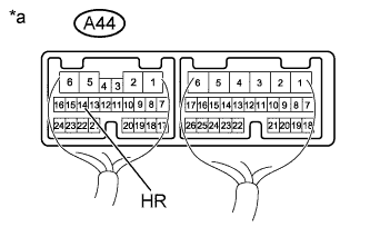
Text in Illustration *a Component with harness connected
(Air Conditioning Amplifier Assembly)
Remove the air conditioning amplifier assembly with its connectors still connected Click here.
-
Measure the voltage according to the value(s) in the table below.
Standard Voltage Tester Connection Switch Condition Specified Condition A44-14 (HR) - Body ground
-
Ignition switch off
-
Blower switch off
Below 1 V
-
Ignition switch ON
-
Blower switch on (LO level)
Below 1 V
-
Ignition switch ON
-
Blower switch off
11 to 14 V -
NG
REPLACE AIR CONDITIONING AMPLIFIER ASSEMBLY Click here
OK 
PROCEED TO NEXT SUSPECTED AREA SHOWN IN PROBLEM SYMPTOMS TABLE Click here
-