WIRELESS DOOR LOCK CONTROL SYSTEM(w/ Entry and Start System) TERMINALS OF ECU
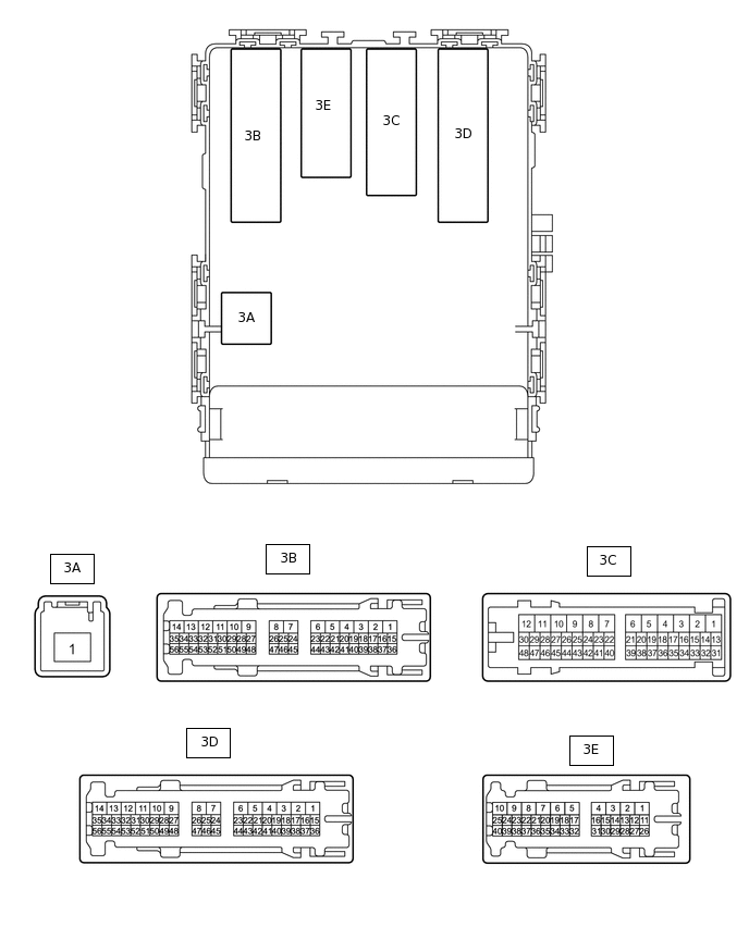
CHECK INSTRUMENT PANEL JUNCTION BLOCK ASSEMBLY AND MAIN BODY ECU (MULTIPLEX NETWORK BODY ECU)
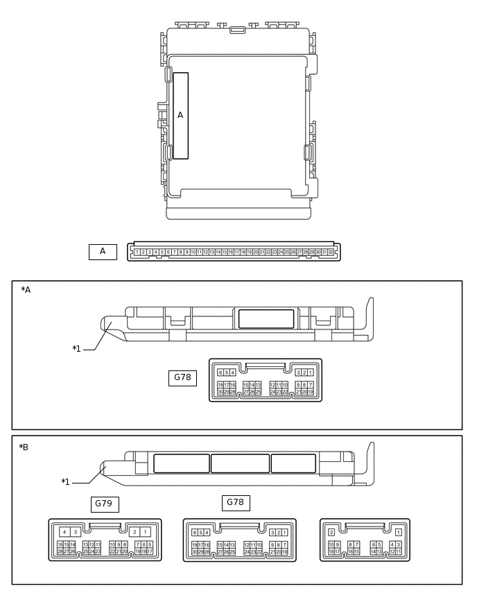
*A
Main Body ECU (Multiplex Network Body ECU) with 1 connector
*B
Main Body ECU (Multiplex Network Body ECU) with 3 connectors
*1
Main Body ECU (Multiplex Network Body ECU)
-
-
Remove the main body ECU (Multiplex network body ECU) from the instrument panel junction block assembly.
for LHD:
for RHD:
Measure the voltage and resistance according to the value(s) in the table below.
Tip:Measure the values on the wire harness side with the connectors disconnected.
Tester Connection
Wiring Color
Terminal Description
Condition
Specified Condition
A-11 (GND1) - Body ground
-
Ground
Always
Below 1 Ω
A-30 (BECU) - Body ground
-
Battery power supply
Always
11 to 14 V
A-29 (ACC) - Body ground
-
ACC power supply
Engine switch on (ACC)
11 to 14 V
A-29 (ACC) - Body ground
-
ACC power supply
Engine switch off
Below 1 V
A-32 (IG) - Body ground
-
Ignition power supply
Engine switch on (IG)
11 to 14 V*1
10.5 to 14 V*2
A-32 (IG) - Body ground
-
Ignition power supply
Engine switch off
Below 1 V
*1: w/o Stop and Start System
*2: w/ Stop and Start System
Install the main body ECU (multiplex network body ECU).
for LHD:
for RHD:
Measure the voltage and check for pulses according to the value(s) in the table below.
Tester Connection
Wiring Color
Terminal Description
Condition
Specified Condition
3E-1 (ACT-) - Body ground
BR - Body ground
Door lock motor unlock drive output (all door)
Door control switch (power window regulator master switch assembly) or driver door key cylinder off
Below 1 V
3E-1 (ACT-) - Body ground
BR - Body ground
Door lock motor unlock drive output (all door)
Door control switch (power window regulator master switch assembly) or driver door key cylinder unlocked
11 to 14 V
3D-5 (ACT-) - Body ground*4
B - Body ground
Door lock motor unlock drive output (all door)
Door control switch (power window regulator master switch assembly) or driver door key cylinder off
Below 1 V
3D-5 (ACT-) - Body ground*4
B - Body ground
Door lock motor unlock drive output (all door)
Door control switch (power window regulator master switch assembly) or driver door key cylinder unlocked
11 to 14 V
3D-4 (ACT-) - Body ground
B - Body ground
Door lock motor unlock drive output (all door)
Door control switch (power window regulator master switch assembly) or driver door key cylinder off
Below 1 V
3D-4 (ACT-) - Body ground
B - Body ground
Door lock motor unlock drive output (all door)
Door control switch (power window regulator master switch assembly) or driver door key cylinder unlocked
11 to 14 V
3D-3 (ACT-) - Body ground
B - Body ground
Door lock motor unlock drive output (all door)
Door control switch (power window regulator master switch assembly) or driver door key cylinder off
Below 1 V
3D-3 (ACT-) - Body ground
B - Body ground
Door lock motor unlock drive output (all door)
Door control switch (power window regulator master switch assembly) or driver door key cylinder unlocked
11 to 14 V
3D-10 (ACTD) - Body ground*3
B - Body ground
Door lock motor unlock drive output (all door)
Door control switch (power window regulator master switch assembly) or driver door key cylinder off
Below 1 V
3D-10 (ACTD) - Body ground*3
B - Body ground
Door lock motor unlock drive output (all door)
Door control switch (power window regulator master switch assembly) or driver door key cylinder unlocked
11 to 14 V
3D-13 (ACT+) - Body ground
R - Body ground
Door lock motor lock drive output (all doors)
Door control switch (power window regulator master switch assembly) or driver door key cylinder locked
11 to 14 V
3D-13 (ACT+) - Body ground
R - Body ground
Door lock motor lock drive output (all doors)
Door control switch (power window regulator master switch assembly) or driver door key cylinder off
Below 1 V
3D-11 (ACT+) - Body ground
R - Body ground
Door lock motor lock drive output (all doors)
Door control switch (power window regulator master switch assembly) or driver door key cylinder locked
11 to 14 V
3D-11 (ACT+) - Body ground
R - Body ground
Door lock motor lock drive output (all doors)
Door control switch (power window regulator master switch assembly) or driver door key cylinder off
Below 1 V
3D-12 (ACT+) - Body ground
R - Body ground
Door lock motor lock drive output (all doors)
Door control switch (power window regulator master switch assembly) or driver door key cylinder locked
11 to 14 V
3D-12 (ACT+) - Body ground
R - Body ground
Door lock motor lock drive output (all doors)
Door control switch (power window regulator master switch assembly) or driver door key cylinder off
Below 1 V
3D-17 (ACT+) - Body ground
R - Body ground
Door lock motor lock drive output (all doors)
Door control switch (power window regulator master switch assembly) or driver door key cylinder locked
Below 1 V
3D-17 (ACT+) - Body ground
R - Body ground
Door lock motor lock drive output (all doors)
Door control switch (power window regulator master switch assembly) or driver door key cylinder locked
11 to 14 V
3E-40 (FLCY) - Body ground
W - Body ground
Front door LH courtesy light switch input
Front door LH open
Below 1 V
3E-40 (FLCY) - Body ground
W - Body ground
Front door LH courtesy light switch input
Front door LH closed
Pulse generation
G78-19 (FRCY) - Body ground
L - Body ground
Front door RH courtesy light switch input
Front door RH open
Below 1 V
G78-19 (FRCY) - Body ground
L - Body ground
Front door RH courtesy light switch input
Front door RH closed
Pulse generation
G78-1 (LCTY) - Body ground*3
W - Body ground
Rear door LH courtesy light switch input
Rear door LH open
Below 1 V
G78-1 (LCTY) - Body ground*3
W - Body ground
Rear door LH courtesy light switch input
Rear door LH closed
Pulse generation
G78-24 (LCTY) - Body ground*4
W - Body ground*1
SB - Body ground*2
Rear door LH courtesy light switch input
Rear door LH open
Below 1 V
G78-24 (LCTY) - Body ground*4
W - Body ground*1
SB - Body ground*2
Rear door LH courtesy light switch input
Rear door LH closed
Pulse generation
G78-6 (RCTY) - Body ground
Y - Body ground
Rear door RH courtesy light switch input
Rear door RH open
Below 1 V
G78-6 (RCTY) - Body ground
Y - Body ground
Rear door RH courtesy light switch input
Rear door RH closed
Pulse generation
G78-7 (LSFL) - Body ground
B - Body ground
Front door LH unlock detection switch input
Front door LH unlocked
Below 1 V
G78-7 (LSFL) - Body ground
B - Body ground
Front door LH unlock detection switch input
Front door LH locked
Pulse generation
G78-18 (LSFR) - Body ground
P - Body ground
Front door RH unlock detection switch input
Front door RH unlocked
Below 1 V
G78-18 (LSFR) - Body ground
P - Body ground
Front door RH unlock detection switch input
Front door RH locked
Pulse generation
3E-32 (LSR) - Body ground
Y - Body ground
Rear door RH unlock detection switch input
Rear door RH or LH unlocked
Below 1 V
3E-32 (LSR) - Body ground
Y - Body ground
Rear door RH unlock detection switch input
Rear door RH and LH locked
Pulse generation
3C-41 (LSR) - Body ground
Y - Body ground
Rear door LH unlock detection switch input
Rear door LH or RH unlocked
Below 1 V
3C-41 (LSR) - Body ground
Y - Body ground
Rear door LH unlock detection switch input
Rear door LH and RH locked
Pulse generation
3B-55 (BZR) - Body ground
L - Body ground
Wireless door lock buzzer signal
Wireless door lock buzzer off
Below 1 V
3B-55 (BZR) - Body ground
L - Body ground
Wireless door lock buzzer signal
Wireless door lock buzzer on
Pulse generation
*1: for LHD
*2: for RHD
*3: w/ Panic Switch
*4: w/o Panic Switch
CHECK CERTIFICATION ECU (SMART KEY ECU ASSEMBLY)
Disconnect the G82 certification ECU (smart key ECU assembly) connector.
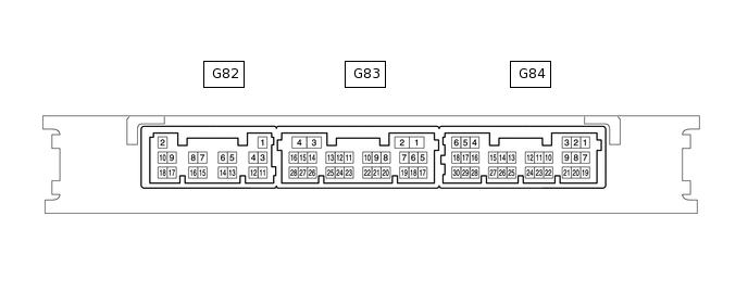
Measure the resistance and voltage according to the value(s) in the table below.
Tip:Measure the values on the wire harness side with the connectors disconnected.
Tester Connection
Wiring Color
Terminal Description
Condition
Specified Condition
G82-11 (E) - Body ground
BR - Body ground
Ground
Always
Below 1 Ω
G82-2 (+B) - Body ground
W - Body ground
Battery power supply
Always
11 to 14 V
G82-10 (CUTB) - Body ground
P - Body ground
Dark current cut fuse pin input signal
Always
11 to 14 V
Reconnect the G82 certification ECU (smart key ECU assembly) connector.
Measure the voltage according to the value(s) in the table below.
Tester Connection
Wiring Color
Terminal Description
Condition
Specified Condition
G84-5 (IG) - G82-11 (E)
LG - BR
Engine switch power supply
Engine switch on (IG)
11 to 14 V
Engine switch off
Below 1 V
G83-6 (CSEL) - G82-11 (E)
BR - BR
Communication channel switching circuit
Engine switch off and all door closed
Below 1 V → 4.5 to 6.0 V → Below 1 V
G83-17 (RDAM) - G82-11 (E)
Y - BR
RF Signal input circuit
Engine switch off, all doors closed and electrical key transmitter sub-assembly switch not pressed → electrical key transmitter sub-assembly switch pressed
11 to 14 V pulse generation at regular intervals → pulse generation
G83-5 (RCO) - G82-11 (E)
V - BR
Wireless tuner power supply output circuit
Engine switch off, all doors closed and electrical key transmitter sub-assembly switch not pressed → electrical key transmitter sub-assembly switch pressed
Below 1 V → 4.5 to 5.5 V
CHECK DOOR CONTROL RECEIVER (for 12 Pin Type)
Disconnect the M11 door control receiver connector.

Measure the resistance according to the value(s) in the table below.
Tip:Measure the values on the wire harness side with the connectors disconnected.
Tester Connection
Wiring Color
Terminal Description
Condition
Specified Condition
M11-12 (E) - Body ground
W-B - Body ground
Ground
Always
Below 1 Ω
Reconnect the M11 door control receiver connector.
Measure the voltage according to the value(s) in the table below.
Tester Connection
Wiring Color
Terminal Description
Condition
Specified Condition
M11-6 (CSEL) - M11-12 (E)
R - W-B
Communication channel switching circuit
Engine switch off and all door closed
Below 1 V → 4.5 to 6.0 V → Below 1 V
M11-9 (DATA) - M11-12 (E)
Y - W-B
Data output
Engine switch off, all doors closed and electrical key transmitter sub-assembly switch not pressed → electrical key transmitter sub-assembly switch pressed
Below 1 V → 10 to 16 V → Below 1 V
M11-10 (+5) - M11-12 (E)
V - W-B
Battery (power supply)
Engine switch off, all doors closed and electrical key transmitter sub-assembly switch not pressed → electrical key transmitter sub-assembly switch pressed
Below 1 V → 4.5 to 5.5 V
CHECK DOOR CONTROL RECEIVER (except 12 Pin Type)
Disconnect the M10 door control receiver connector.

Measure the resistance according to the value(s) in the table below.
Tip:Measure the values on the wire harness side with the connectors disconnected.
Tester Connection
Wiring Color
Terminal Description
Condition
Specified Condition
M10-1 (GND) - Body ground
W-B - Body ground
Ground
Always
Below 1 Ω
Reconnect the M10 door control receiver connector.
Measure the voltage according to the value(s) in the table below.
Tester Connection
Wiring Color
Terminal Description
Condition
Specified Condition
M10-2 (CSEL) - M10-1 (GND)
R - W-B
Communication channel switching circuit
Engine switch off and all door closed
Below 1 V → 4.5 to 6.0 V → Below 1 V
M10-5 (DATA) - M10-1 (GND)
Y - W-B
Data output
Engine switch off, all doors closed and electrical key transmitter sub-assembly switch not pressed → electrical key transmitter sub-assembly switch pressed
Below 1 V → 10 to 16 V → Below 1 V
M10-4 (+5) - M10-1 (GND)
V - W-B
Battery (power supply)
Engine switch off, all doors closed and electrical key transmitter sub-assembly switch not pressed → electrical key transmitter sub-assembly switch pressed
Below 1 V → 4.5 to 5.5 V