HAZARD WARNING SWITCH INSPECTION
PROCEDURE
-
INSPECT HAZARD WARNING SIGNAL SWITCH ASSEMBLY
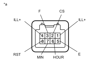
Text in Illustration *a Component without harness connected
(Hazard Warning Signal Switch Assembly)
-
Hazard Warning Switch Inspection
-
Measure the resistance according to the value(s) in the table below.
Standard Resistance Tester Connection Condition Specified Condition 3 (F) - 5 (E) Hazard warning switch not pressed 10 kΩ or higher Hazard warning switch pressed Below 1 Ω
-
-
Rheostat Switch (Pattern Select Switch) Inspection
-
Measure the resistance according to the value(s) in the table below.
Standard Resistance Tester Connection Condition Specified Condition 2 (CS) - 5 (E) Rheostat switch (pattern select switch) not pressed 10 kΩ or higher Rheostat switch (pattern select switch) pressed Below 1 Ω
-
-
Time Adjust Switch Inspection
-
Measure the resistance according to the value(s) in the table below.
Standard Resistance Tester Connection Condition Specified Condition 6 (HOUR) - 5 (E) Hour adjust switch not pressed 10 kΩ or higher Hour adjust switch pressed Below 1 Ω 7 (MIN) - 5 (E) Minute adjust switch not pressed 10 kΩ or higher Minute adjust switch pressed Below 1 Ω 8 (RST) - 5 (E) Second adjust switch not pressed 10 kΩ or higher Second adjust switch pressed Below 1 Ω
-
-
Illumination Inspection
-
Apply auxiliary battery voltage to the hazard warning signal switch and check that the switch illuminates.
OK Tester Connection Specified Condition Auxiliary battery positive (+) → Terminal 4 (ILL+)
Auxiliary battery negative (-) → Terminal 1 (ILL-)
Illuminates If the result is not as specified, replace the integration control and panel sub-assembly.
-
-