PARKING SUPPORT ALERT SYSTEM TERMINALS OF ECU
-
CLEARANCE WARNING ECU ASSEMBLY

-
Disconnect the L18 clearance warning ECU assembly connector.
-
Measure the voltage and resistance on the wire harness side connector according to the value(s) in the table below.
Terminal No. (Symbol) Wiring Color Terminal Description Condition Specified Condition L18-1 (IG) - L18-30 (E) R - W-B IG power source signal Engine switch off Below 1 V Engine switch on (IG) 10.5 to 16 V L18-30 (E) - Body ground W-B - Body ground Ground Always Below 1 Ω -
Reconnect the L18 clearance warning ECU assembly connector.
-
Measure the voltage and check for pulses according to the value(s) in the table below.
Terminal No. (Symbol) Wiring Color Terminal Description Condition Specified Condition L18-4 (BOF) - L18-30 (E) R - W-B Power source for front sensor circuit
-
Engine switch on (IG)
-
Parking support alert system on
11 to 14 V L18-6 (E5) - L18-30 (E) G - W-B Ground for front clearance sonar Always Below 1 Ω L18-8 (SOF) - L18-30 (E) W - W-B Front sensor communication signal (Front clearance sonar sensor)
-
Engine running
-
Parking support alert system on
-
Shift position in any position other than P or R
-
Vehicle speed is less than approximately 10 km/h (6 mph)
Pulse generation
(Refer to waveform 1)
L18-14 (CBZ) - L18-13 (EF) LG - L No. 1 clearance warning buzzer signal Buzzer sounding Pulse generation
(Refer to waveform 2)
L18-15 (BBZ) - L18-16 (ER) L - R No. 2 clearance warning buzzer signal Buzzer sounding Pulse generation
(Refer to waveform 2)
L18-22 (BOR) - L18-30 (E) GR - W-B Power source for rear sensor circuit
-
Engine switch on (IG)
-
Parking support alert system on
11 to 14 V L18-23 (E1) - L18-30 (E) W - W-B Ground for rear clearance sonar Always Below 1 Ω L18-24 (SOR) - L18-30 (E) P - W-B Rear sensor communication signal (Rear clearance sonar sensor)
-
Engine running
-
Parking support alert system on
-
Shift position in R
-
Vehicle speed is less than approximately 10 km/h (6 mph)
Pulse generation
(Refer to waveform 1)
L18-28 (STP) - L18-30 (E)*1 R - W-B Reverse signal
-
Engine running
-
Shift position not in R
Below 3 V
-
Engine running
-
Shift position in R
8 V or higher L18-31 (IND) - L18-30 (E)*1 B - W-B Reverse signal
-
Engine running
-
Shift position not in R
8 V or higher
-
Engine running
-
Shift position in R
Below 3 V
-
*1: w/ Parking Assist Monitor System
-
-
Using an oscilloscope, check waveform 1.
-
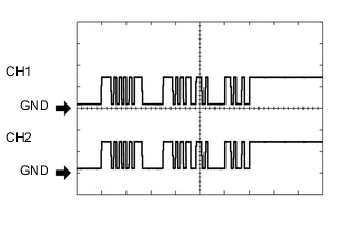
Waveform 1 (Reference)
Item Content Measurement terminal
-
CH1: L18-8 (SOF) - L18-30 (E)
-
CH2: L18-24 (SOR) - L18-30 (E)
Measurement setting 5 V/DIV., 1 ms./DIV. Condition
-
Engine running
-
Parking support alert system on
-
Shift position in any position other than P or R (CH1)
-
Shift position in R (CH2)
-
Vehicle speed is less than approximately 10 km/h (6 mph) (CH1)
Tech Tips
The waveforms for CH1 and CH2 are same.
-
-
-
Using an oscilloscope, check waveform 2.
-
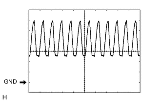
Waveform 2 (Reference)
Item Content Measurement terminal L18-14 (CBZ) - L18-13 (EF)
L18-15 (BBZ) - L18-16 (ER)
Measurement setting 2 V/DIV., 500 μs./DIV. Condition Buzzer sounding Tech Tips
The amplitude of the waveform changes according to the set volume.
-
-
-
BLIND SPOT MONITOR SENSOR RH (w/ Blind Spot Monitor System)
-
BLIND SPOT MONITOR SENSOR LH (w/ Blind Spot Monitor System)
-
REAR TELEVISION CAMERA ASSEMBLY (w/ Blind Spot Monitor System and w/ Panoramic View Monitor System)