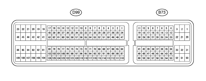
ECD SYSTEM (w/ DPF) TERMINALS OF ECM
Tech Tips
Each ECM terminal's standard voltage is shown in the table below.
In the table, first follow the information under "Condition". Look under "Terminal No. (Symbol)" for the terminals to be inspected. The standard voltage between the terminals is shown under "Specified Condition".
Use the illustration above as a reference for the ECM terminals.
| Terminal No. (Symbol) | Wiring Color | Terminal Description | Condition | Specified Condition |
|---|---|---|---|---|
| B73-2 (BATT) - D99-109 (E1) | W - W-B | Battery (for measuring the battery voltage and for the ECM memory) | Always | 11 to 14 V |
| B73-25 (IGSW) - D99-109 (E1) | B - W-B | Ignition switch | Ignition switch ON | 11 to 14 V |
| B73-1 (+B) - D99-109 (E1) | L - W-B | Power source of ECM | Ignition switch ON | 11 to 14 V |
| B73-20 (+B2) - D99-109 (E1) | L - W-B | Power source of ECM | Ignition switch ON | 11 to 14 V |
| B73-45 (MREL) - D99-109 (E1) | G - W-B | EFI MAIN relay | Ignition switch ON | 11 to 14 V |
| 10 seconds elapsed after ignition switch off | 0 to 1.5 V | |||
| B73-55 (VCPA) - B73-56 (EPA) | W - G | Power source of accelerator pedal position sensor (for VPA) | Ignition switch ON | 4.5 to 5.5 V |
| B73-57 (VCP2) - B73-58 (EPA2) | R - GR | Power source of accelerator pedal position sensor (for VPA2) | Ignition switch ON | 4.5 to 5.5 V |
| B73-53 (VPA) - B73-56 (EPA) | L - G | Accelerator pedal position sensor (for engine control) | Ignition switch ON, accelerator pedal fully released | 0.5 to 1.1 V |
| Ignition switch ON, accelerator pedal fully depressed | 3.0 to 4.6 V | |||
| B73-54 (VPA2) - B73-58 (EPA2) | B - GR | Accelerator pedal position sensor (for sensor malfunction detection) | Ignition switch ON, accelerator pedal fully released | 0.9 to 2.3 V |
| Ignition switch ON, accelerator pedal fully depressed | 3.4 to 5.0 V | |||
| D99-75 (VCPX) - D99-74 (EPEX) | L - Y | Power source for sensor (specific voltage) | Ignition switch ON | 4.5 to 5.0 V |
| D99-65 (VG) - D99-64 (EVG) | B-L - B | Mass air flow meter | Idling | Pulse generation |
| D99-110 (THA) - D99-87 (ETHA) | R - Y-R | Intake air temperature sensor (built into mass air flow meter) | Idling, intake air temperature at 20°C (68°F) | 0.5 to 3.4 V |
| D99-113 (THIA) - D99-90 (ETHI) | R - B | Intake air temperature sensor | Idling, intake air temperature at 0 to 80°C (32 to 176°F) | 0.5 to 3.4 V |
| D99-111 (THW) - D99-88 (ETHW) | R-W - G | Engine coolant temperature sensor | Idling, engine coolant temperature at 80°C (176°F) | 0.2 to 1.0 V |
| D99-112 (THF) - D99-89 (ETHF) | R - Y | Fuel temperature sensor | Ignition switch ON | 0.5 to 3.4 V |
| B73-43 (STA) - D99-109 (E1) | R - W-B | Starter signal | Cranking | 6.0 V or higher |
| D99-50 (#1) - D99-109 (E1) | G - W-B | Injector assembly | Idling | Pulse generation (See waveform 2) |
| D99-49 (#2) - D99-109 (E1) | GR - W-B | |||
| D99-48 (#3) - D99-109 (E1) | Y - W-B | |||
| D99-47 (#4) - D99-109 (E1) | B - W-B | |||
| D99-80 (G+) - D99-79 (G-) | R - G | Camshaft position sensor | Idling | Pulse generation (See waveform 5) |
| D99-103 (NE+) - D99-102 (NE-) | B - W | Crankshaft position sensor | Idling | Pulse generation (See waveform 5) |
| B73-35 (STP) - D99-109 (E1) | Y - W-B | Stop light switch assembly | Ignition switch ON, brake pedal depressed | 7.5 to 14 V |
| Ignition switch ON, brake pedal released | 0 to 1.5 V | |||
| B73-34 (ST1-) - D99-109 (E1) | R - W-B | Stop light switch assembly (opposite to STP) |
Ignition switch ON, brake pedal depressed | 0 to 1.5 V |
| Ignition switch ON, brake pedal released | 7.5 to 14 V | |||
| D99-73 (CLSW)*1 - D99-109 (E1) | R - W-B | Clutch switch assembly | Ignition switch ON, clutch pedal released | 8.5 to 14 V |
| B73-26 (TC) - D99-109 (E1) | G - W-B | Terminal TC of DLC3 | Ignition switch ON | 11 to 14 V |
| B73-14 (SPD) - D99-109 (E1) | P - W-B | Speed signal from combination meter assembly | Ignition switch ON, slowly wheel rotated | Pulse generation (See waveform 9) |
| D99-93 (VCPM) - D99-72 (EPIM) | W - G | Power source of manifold absolute pressure sensor | Ignition switch ON | 4.5 to 5.5 V |
| D99-117 (PIM) - D99-72 (EPIM) | P - G | Manifold absolute pressure sensor | Negative pressure of 40 kPa (300 mmHg, 11.8 in.Hg) applied | 0.1 to 0.7 V |
| Same as atmospheric pressure | 0.8 to 1.5 V | |||
| Positive pressure of 170 kPa (1275 mmHg, 50.2 in.Hg) applied | 1.6 to 2.3 V | |||
| B73-44 (IREL) - D99-109 (E1) | R - W-B | EDU relay | Ignition switch ON | 0 to 1.5 V |
| B73-13 (TACH) - D99-109 (E1) | B - W-B | Engine speed | Idling | Pulse generation |
| D99-68 (VCS) - D99-67 (E2S) | G-B - G | Power source of fuel pressure sensor (for PCR1) | Ignition switch ON | 4.5 to 5.5 V |
| D99-69 (VCS2) - D99-91 (E2S2) | G - Y | Power source of fuel pressure sensor (for PCR2) | Ignition switch ON | 4.5 to 5.5 V |
| D99-66 (PCR1) - D99-91 (E2S2) | P - Y | Fuel pressure sensor (main) | Idling | 1.8 to 2.1 V |
| D99-114 (PCR2) - D99-67 (E2S) | G-R - G | Fuel pressure sensor (sub) | Idling | 1.2 to 1.5 V |
| D99-54 (ALT) - D99-109 (E1) | W - W-B | Generator assembly (Alternator) duty ratio | Idling | Pulse generation |
| D99-98 (PEX) - D99-74 (EPEX) | G - Y | Differential pressure sensor | Ignition switch ON | 0.4 to 4.8 V |
| D99-104 (HAF2) - D99-46 (E05) | W - W-B | Air fuel ratio sensor heater | Ignition switch ON | 11 to 14 V |
| D99-125 (AF2+) - D99-46 (E05) | L - W-B | Air fuel ratio sensor | Ignition switch ON | 2.0 to 2.5 V |
| D99-126 (AF2-) - D99-46 (E05) | Y - W-B | Air fuel ratio sensor | Ignition switch ON | 2.0 to 2.5 V |
| D99-105 (FIV) - D99-109 (E1) | B - W-B | Exhaust fuel addition injector | Exhaust fuel addition injector operating | Pulse generation |
| D99-41 (PCV+) - D99-81 (PCV-) | P - Y | Suction control valve | Idling | Pulse generation (See waveform 1) |
| D99-51 (INJF) - D99-109 (E1) | LG - W-B | Injector driver | Idling | Pulse generation (See waveform 3) |
| D99-52 (PRD) - D99-109 (E1) | V - W-B | Pressure discharge valve drive signal | Engine warmed up, engine racing | Pulse generation (See waveform 4) |
| D99-123 (RLFF) - D99-109 (E1) | R - W-B | Pressure discharge valve confirmation signal | Engine warmed up, engine racing | Pulse generation (See waveform 4) |
| D99-62 (IDLO) - D99-109 (E1) | P - W-B | EDU | Idling | 4 to 5.5 V |
| D99-39 (EOPV) - D99-109 (E1) | R - W-B | Oil pressure switching valve | Idling | 0 to 1.5 V |
| D99-42 (M+) - D99-109 (E1) | R - W-B | DC motor (turbocharger sub-assembly) | Idling | Pulse generation (See waveform 6) |
| D99-43 (M-) - D99-109 (E1) | G - W-B | DC motor (turbocharger sub-assembly) | Idling | Pulse generation (See waveform 7) |
| D99-94 (VNVC) - D99-95 (VNE2) | G - R | Power source of nozzle vane position sensor | Ignition switch ON | 4.5 to 5.5 V |
| D99-116 (VNA) - D99-95 (VNE2) | R-W - R | Nozzle vane position sensor | Ignition switch ON | 2.3 to 2.7 V |
| D99-97 (VCVL) - D99-96 (EVLU) | L- Y | Power source of throttle position sensor | Ignition switch ON | 4.5 to 5.5 V |
| D99-119 (VLU) - D99-96 (EVLU) | R- Y | Throttle position sensor | Ignition switch ON, throttle valve fully opened |
3.6 to 4.2 V |
| Ignition switch ON, throttle valve fully closed |
0.4 to 1.0 V | |||
| D99-78 (LUSL) - D99-109 (E1) | B - W-B | Diesel throttle duty signal | Engine warmed up, racing engine | Pulse generation (See waveform 8) |
| D99-115 (EGRA) - D99-92 (EEGL) | G - Y | EGR valve position sensor | Ignition switch ON | 0.6 to 1.4 V |
| D99-86 (EGM+) - D99-84 (ME01) | B - W-B | EGR valve duty signal | Engine warmed up, idling | Pulse generation |
| D99-85 (EGM-) - D99-84 (ME01) | W - W-B | EGR valve duty signal | Engine warmed up, idling | Pulse generation |
| D99-106 (ECBV) - D99-109 (E1) | R - W-B | Vacuum switching valve (for EGR bypass valve) | Vacuum switching valve assembly (for EGR bypass valve) on | 0 to 1.5 V |
| Vacuum switching valve assembly (for EGR bypass valve) off | 11 to 14 V | |||
| D99-76 (THCF) - D99-77 (ETCF) | W - L | Exhaust gas temperature sensor | Engine warmed up, idling | 4.6 to 4.9 V |
| D99-122 (THCI) - D99-99 (ETCI) | L - R | No. 2 Exhaust gas temperature sensor | Engine warmed up, idling | 4.6 to 4.9 V |
| D99-121 (THCO) - D99-120 (ETCO) | B - Y | No. 3 Exhaust gas temperature sensor | Engine warmed up, idling | 4.6 to 4.9 V |
| D99-108 (SCV) - D99-45 (E01) | W - W-B | Vacuum switching valve (for No. 1 swirl control valve) | Idling | 0 to 1.5 V |
| Engine speed 2600 rpm or more | 11 to 14 V | |||
| D99-107 (SCV2) - D99-45 (E01) | W - W-B | Vacuum switching valve (for No. 2 swirl control valve) | Idling | 0 to 1.5 V |
| Engine speed 2600 rpm or more | 11 to 14 V | |||
| B73-59 (RTHW) - D99-74 (EPEX) | L - Y | Engine coolant temperature (radiator) sensor | Idling, engine coolant temperature (radiator) at -20 to 80°C (-4° to 176°F) | 0.5 to 4.5 V |
| D99-118 (POP) - D99-74 (EPEX) | R - Y | Oil pressure sender gauge assembly | Engine running | 0.1 to 0.9 V |
| B73-49 (RFC) - D99-109 (E1) | LG - W-B | No. 1 Cooling Fan ECU | No. 1 cooling fan operating | Pulse generation (See waveform 10) |
| B73-48 (RFC2) - D99-109 (E1) | P - W-B | No. 2 Cooling Fan ECU | No. 2 cooling fan operating | Pulse generation (See waveform 10) |
| D99-38 (NSW)*2 - D99-45 (E01) | B - W-B | Park/neutral position switch assembly | Ignition switch ON, shift lever in P or N | Below 3 V |
| Ignition switch ON, shift lever not in P and N | 11 to 14 V | |||
| B73-6 (CANL) - D99-109 (E1) | W - W-B | CAN communication line | Ignition switch ON | Pulse generation (See waveform 11) |
| B73-7 (CANH) - D99-109 (E1) | B - W-B | CAN communication line | Ignition switch ON | Pulse generation (See waveform 12) |
| D99-63 (CAN-)*2 - D99-109 (E1) | Y - W-B | CAN communication line | Ignition switch ON | Pulse generation (See waveform 11) |
| D99-40 (CAN+)*2 - D99-109 (E1) | L - W-B | CAN communication line | Ignition switch ON | Pulse generation (See waveform 12) |
Tech Tips
-
*1: for Manual Transmission
-
*2: for Automatic Transmission
-
WAVEFORM 1
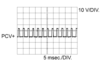
Suction Control Valve Signal Item Content Terminal No. (Symbol) D99-41 (PCV+) - D99-81 (PCV-) Tool Setting 10 V/DIV., 5 msec./DIV. Condition Idling or cranking with warm engine Tech Tips
The waveform varies depending on suction control valve operation.
-
WAVEFORM 2
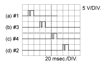
Injector No. 1 (to No. 4) Injection Signal Item Content Terminal No. (Symbol) (a) D99-50 (#1) - D99-109 (E1)
(b) D99-49 (#2) - D99-109 (E1)
(c) D99-48 (#3) - D99-109 (E1)
(d) D99-47 (#4) - D99-109 (E1)
Tool Setting 5 V/DIV., 20 msec./DIV. Condition Idling with warm engine Tech Tips
The waveform varies depending on the injector injection.
-
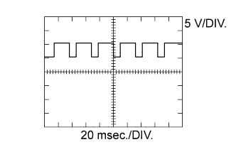
WAVEFORM 3
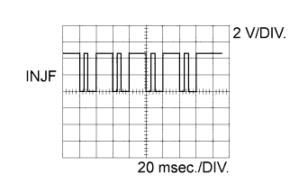
Injector Injection Confirmation Signal Item Content Terminal No. (Symbol) D99-51 (INJF) - D99-109 (E1) Tool Setting 2 V/DIV., 20 msec./DIV. Condition Idling with warm engine Tech Tips
The waveform varies depending on the injector injection.
-
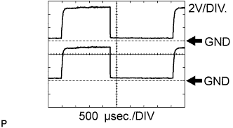
WAVEFORM 4
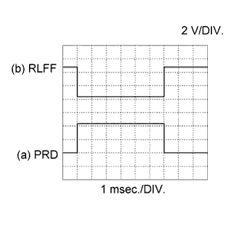
Pressure Discharge Valve Drive Signal and Pressure Discharge Confirmation Signal Item Content Terminal No. (Symbol) (a) D99-52 (PRD) - D99-109 (E1)
(b) D99-123 (RLFF) - D99-109 (E1)
Tool Setting 2 V/DIV., 1 msec./DIV. Condition Engine warmed up, engine racing Tech Tips
The wavelength becomes shorter as the engine speed.
-
WAVEFORM 5
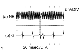
Crankshaft Position Sensor Signal and Camshaft Position Sensor Signal Item Content Terminal No. (Symbol) (a) D99-103 (NE+) - D99-102 (NE-)
(b) D99-80 (G+) - D99-79 (G-)
Tool Setting 5 V/DIV., 20 msec./DIV. Condition Idling with warm engine Tech Tips
The waveform varies depending on the engine speed.
-
WAVEFORM 6
DC Motor Positive Terminal Item Content Terminal No. (Symbol) D99-42 (M+) - D99-109 (E1) Tool Setting 5 V/DIV., 20 msec./DIV. Condition Idling with warm engine Tech Tips
The waveform varies depending on turbocharger operation.
-
WAVEFORM 7
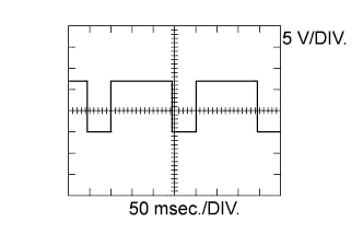
DC Motor Negative Terminal Item Content Terminal No. (Symbol) D99-43 (M-) - D99-109 (E1) Tool Setting 5 V/DIV., 50 msec./DIV. Condition Idling with warm engine Tech Tips
The waveform varies depending on the turbocharger status.
-
WAVEFORM 8
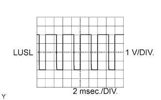
Diesel Throttle Signal Item Content Terminal No. (Symbol) D99-78 (LUSL) - D99-109 (E1) Tool Setting 1 V/DIV., 2 msec./DIV. Condition Racing with warm engine Tech Tips
The waveform varies depending on throttle valve operation.
-
WAVEFORM 9
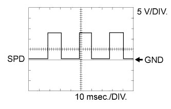
Vehicle Speed Signal Item Content Terminal No. (Symbol) B73-14 (SPD) - D99-109 (E1) Tool Setting 5 V/DIV., 10 msec./DIV. Condition Driving at vehicle speed of 40 km/h (25 mph) Tech Tips
The wavelength becomes shorter as the vehicle speed increases.
-
WAVEFORM 10
Cooling Fan ECU Signal Item Content Terminal No. (Symbol) B73-49 (RFC) - D99-109 (E1)
B73-48 (RFC2) - D99-109 (E1)
Tool Setting 2 V/DIV., 500 msec./DIV. Condition Cooling fan operating -
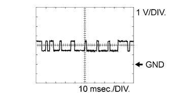
WAVEFORM 11
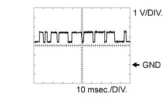
CAN Communication Signal Item Content Terminal No. (Symbol) B73-6 (CANL) - D99-109 (E1)
D99-63 (CAN-) - D99-109 (E1)
Tool Setting 1 V/DIV., 10 msec./DIV. Condition Engine stopped, ignition switch ON Tech Tips
The waveform varies depending on the CAN communication signal.
-
WAVEFORM 12
CAN Communication Signal Item Content Terminal No. (Symbol) B73-7 (CANH) - D99-109 (E1)
D99-40 (CAN+) - D99-109 (E1)
Tool Setting 1 V/DIV., 10 msec./DIV. Condition Engine stopped, ignition switch ON Tech Tips
The waveform varies depending on the CAN communication signal.