NAVIGATION SYSTEM AVC-LAN Circuit
| DTC Code | DTC Name |
|---|---|
| AVC-LAN Circuit |
DESCRIPTION
Each audio system component connected to the AVC-LAN (communication bus) transfers switch signals using the audio visual communication local area network.
If a short to +B or short to ground occurs in the AVC-LAN, the audio system will not function normally because communication is not possible.
WIRING DIAGRAM
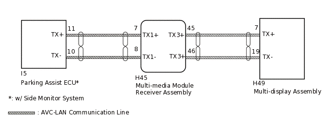
PROCEDURE
INSPECT MULTI-MEDIA MODULE RECEIVER ASSEMBLY
Remove the multi-media module receiver assembly with the connector(s) still connected.
-
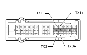
Measure the resistance according to the value(s) in the table below.
Standard Resistance
Tester Connection
Condition
Specified Condition
7 (TX1+) - 8 (TX1-)
Always
60 to 80 Ω
45 (TX3+) - 46 (TX3-)
Always
60 to 80 Ω
Result
Proceed to
OK
NG
CHECK HARNESS AND CONNECTOR (AVC-LAN CIRCUIT)
*: w/ Side Monitor System
Disconnect the H45 multi-media module receiver assembly connector.
Disconnect the H49 multi-display assembly connector.
Disconnect the I5 parking assist ECU connector.*
Measure the resistance according to the value(s) in the table below.
Standard Resistance
Tester Connection
Condition
Specified Condition
H45-45 (TX3+) - H49-7 (TX+)
Always
Below 1 Ω
H45-46 (TX3-) - H49-19 (TX-)
Always
Below 1 Ω
H45-7 (TX1+) - I5-11 (TX+)*
Always
Below 1 Ω
H45-8 (TX1-) - I5-10 (TX-)*
Always
Below 1 Ω
H45-45 (TX3+) - Body ground
Always
10 kΩ or higher
H45-46 (TX3-) - Body ground
Always
10 kΩ or higher
H45-7 (TX1+) - Body ground*
Always
10 kΩ or higher
H45-8 (TX1-) - Body ground*
Always
10 kΩ or higher
Result
Proceed to
OK
NG
NG REPAIR OR REPLACE HARNESS OR CONNECTOR
INSPECT MALFUNCTIONING PARTS
Disconnect and reconnect each slave unit one by one until the master unit returns to normal operation.
Tip:Check all slave units.
When disconnecting a slave unit causes the master unit to return to normal operation, this indicates that the slave unit is malfunctioning. Replace the malfunctioning slave unit.
OK
Master unit returns to normal operation.
Result
Proceed to
OK
NG
OK REPLACE MALFUNCTIONING PARTS