AIR FUEL RATIO SENSOR(w/ Glow Plug Controller) INSTALLATION
PROCEDURE
INSTALL AIR FUEL RATIO SENSOR (for Sensor 2)
-
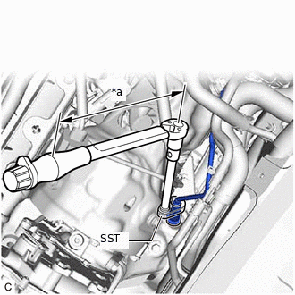
*a
Torque Wrench Fulcrum Length
Using SST, install the air fuel ratio sensor to the exhaust manifold.
09224-00011
Specified tightening torque
44 N*m
449 kgf*cm
32 ft.*lbf
Note:If the air fuel ratio sensor has been struck or dropped, replace it.
Tip:Calculate the torque wrench reading when changing the fulcrum length of the torque wrench.
When using SST (fulcrum length of 30 mm (1.18 in.)) + torque wrench (fulcrum length of 255 mm (10.0 in.)):
39 N*m (398 kgf*cm, 29 ft.*lbf)
Engage the 3 wire harness clamps.
-
INSTALL AIR FUEL RATIO SENSOR (for Sensor 1)
-
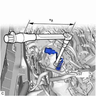
*a
Torque Wrench Fulcrum Length
Using SST, install the air fuel ratio sensor to the exhaust manifold.
09224-00011
Specified tightening torque
44 N*m
449 kgf*cm
32 ft.*lbf
Note:If the air fuel ratio sensor has been struck or dropped, replace it.
Tip:Calculate the torque wrench reading when changing the fulcrum length of the torque wrench.
When using SST (fulcrum length of 30 mm (1.18 in.)) + torque wrench (fulcrum length of 255 mm (10.0 in.)):
39 N*m (398 kgf*cm, 29 ft.*lbf)
-
INSTALL NO. 2 ENGINE COVER BRACKET
Install the No. 2 engine cover bracket with the 2 nuts.
11 N*m
112 kgf*cm
8 ft.*lbf
INSTALL WIRE HARNESS CLAMP BRACKET
Install the wire harness clamp bracket to the No. 2 engine cover bracket with the 2 bolts.
12.5 N*m
127 kgf*cm
9 ft.*lbf
Engage the wire harness clamp.
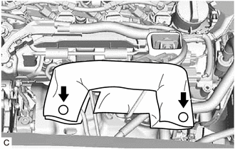
INSTALL NO. 1 WIRE HARNESS HEAT INSULATOR
-
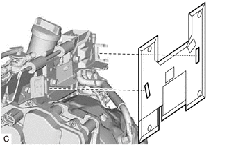
Install the No. 1 wire harness heat insulator to the wire harness clamp bracket.
Tip:Do not fasten the buttons.
-
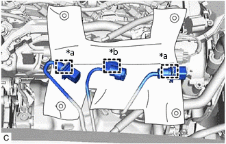
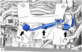
*a
Air Fuel Ratio Sensor Connector
*b
Exhaust Gas Temperature Sensor Connector
Engage the exhaust gas temperature sensor connector to the wire harness clamp bracket.
Engage the 2 air fuel ratio sensor connectors to the wire harness clamp bracket.
-
*a
Air Fuel Ratio Sensor Connector
*b
Exhaust Gas Temperature Sensor Connector
Engage the clamp.
Connect the exhaust gas temperature sensor connector.
Connect the 2 air fuel ratio sensor connectors.
-
Fasten the 2 buttons.
-
INSTALL NO. 1 ENGINE COVER (w/ No. 1 Engine Cover)
INSTALL OUTER COWL TOP PANEL
for LHD:
for RHD:
INSTALL NO. 2 HEATER AIR DUCT SPLASH SHIELD SEAL
for LHD:
for RHD:
INSTALL WATER GUARD PLATE LH
for LHD:
for RHD:
INSTALL WINDSHIELD WIPER MOTOR AND LINK ASSEMBLY
INSPECT FOR EXHAUST GAS LEAK
PERFORM INITIALIZATION
Perform "A/F Sensor Compensation Reset" after replacing an air fuel ratio sensor.