CAMSHAFT(w/ Glow Plug Controller) REMOVAL
PROCEDURE
INSTALL ENGINE TO ENGINE STAND
REMOVE ENGINE COVER BRACKET
REMOVE GENERATOR ASSEMBLY
REMOVE GENERATOR BRACKET
REMOVE EGR WITH COOLER PIPE ASSEMBLY
REMOVE NO. 1 EGR COOLER BRACKET
REMOVE HARNESS BRACKET (for LHD)
REMOVE HARNESS BRACKET (for RHD)
REMOVE EGR VALVE (ELECTRIC EGR CONTROL VALVE ASSEMBLY)
REMOVE ENGINE OIL LEVEL DIPSTICK
REMOVE ENGINE OIL LEVEL DIPSTICK GUIDE
REMOVE INTAKE AIR CONNECTOR WITH DIESEL THROTTLE BODY
DISCONNECT NOZZLE LEAKAGE PIPE ASSEMBLY
REMOVE FUEL INLET PIPE SUB-ASSEMBLY
DISCONNECT NO. 1 FUEL HOSE
DISCONNECT NO. 2 FUEL HOSE
-
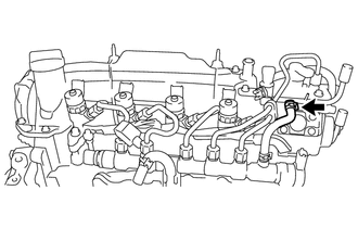
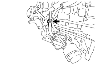
Slide the hose clip and disconnect the No. 2 fuel hose from the No. 2 nozzle leakage pipe.
-
REMOVE NO. 2 NOZZLE LEAKAGE PIPE
REMOVE FUEL PUMP PROTECTOR
REMOVE SUPPLY PUMP ASSEMBLY
REMOVE NO. 2 OIL COOLER HOSE
REMOVE NO. 4 WATER BY-PASS HOSE
-
Disengage the clamp to separate the No. 4 water by-pass hose from the common rail assembly.
Slide the hose clip and remove the No. 4 water by-pass hose from the water inlet pipe.
-
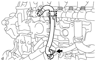
REMOVE WATER BY-PASS PIPE SUB-ASSEMBLY
-
Slide the hose clip and disconnect the No. 6 water by-pass hose from the water by-pass pipe sub-assembly.
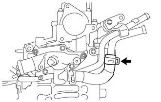
-
Slide the hose clip and disconnect the water by-pass hose from the tube connector.
-
Slide the hose clip and disconnect the oil cooler hose from the water by-pass pipe sub-assembly.
-
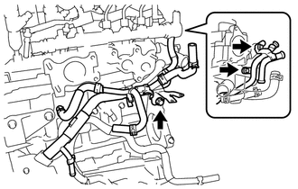
Remove the 3 bolts and water by-pass pipe sub-assembly from the No. 2 turbocharger stay, cylinder head sub-assembly, cylinder block sub-assembly and water inlet housing.
Remove the O-ring from the water by-pass pipe sub-assembly.
-
REMOVE VACUUM PUMP ASSEMBLY
REMOVE V-RIBBED BELT TENSIONER ASSEMBLY
REMOVE CYLINDER HEAD COVER SUB-ASSEMBLY
REMOVE ENGINE MOUNTING BRACKET RH
REMOVE NO. 2 TIMING CHAIN COVER
REMOVE CAMSHAFT POSITION SENSOR
REMOVE CRANKSHAFT DAMPER SUB-ASSEMBLY
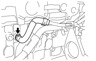
DISCONNECT WATER INLET HOSE LH
-
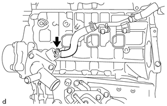
Slide the hose clip and disconnect the water inlet hose LH from the water inlet.
-
REMOVE TIMING CHAIN COVER SUB-ASSEMBLY
REMOVE TIMING CHAIN COVER OIL SEAL
REMOVE NO. 1 CHAIN TENSIONER ASSEMBLY
REMOVE CHAIN TENSIONER SLIPPER
REMOVE NO. 1 CHAIN VIBRATION DAMPER
REMOVE CHAIN SUB-ASSEMBLY
REMOVE CAMSHAFT
-
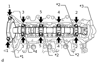
*1
No. 1 Camshaft Bearing Cap
*2
No. 2 Camshaft Bearing Cap
*3
No. 3 Camshaft Bearing Cap
*4
No. 4 Camshaft Bearing Cap
Remove the 10 bolts from the No. 1 camshaft bearing cap, 3 No. 2 camshaft bearing caps and No. 4 camshaft bearing cap by loosening them in the order shown in the illustration, and then remove the No. 1 camshaft bearing cap, 3 No. 2 camshaft bearing caps and No. 4 camshaft bearing cap from the cylinder head sub-assembly.
Note:Using several steps, uniformly loosen the bolts while keeping the camshaft level.
Do not remove the No. 3 camshaft bearing cap.
Remove the camshaft from the cylinder head sub-assembly.
-