BLIND SPOT MONITOR SYSTEM
-
FUNCTION OF MAIN COMPONENTS
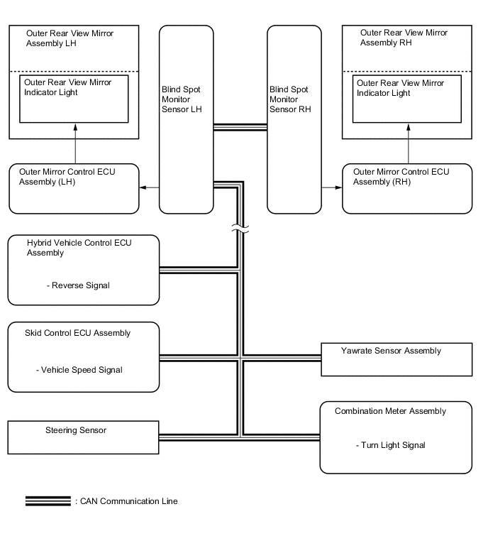
Component Function Blind Spot Monitor Sensor LH and RH
-
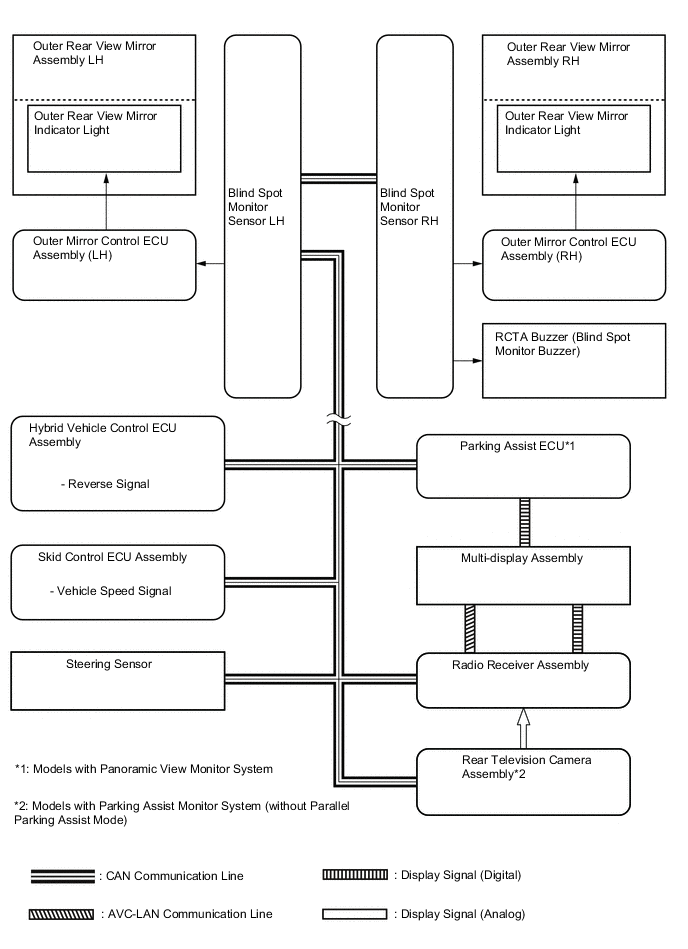
Outputs millimeter waves from the blind spot monitor sensor to the blind spot sensor detection area, uses the reflected millimeter waves for detecting the presence of a vehicle, the vehicle-to-vehicle distance, and the relative speed, and then sends this information to the built-in signal processing circuit.
-
The signal processing circuit determines if a vehicle is present, and illuminates or blinks the outer rear view mirror indicator accordingly.
-
Dims the outer rear view mirror indicator light on the outer rear view mirror assembly.
-
Sends the indicator light signal to the outer mirror control ECU assembly LH/RH.
Outer Rear View Mirror Assembly LH and RH Outer Rear View Mirror Indicator Light
-
Illuminates to inform the driver that a vehicle has been detected in the blind spot monitor sensor detection area.
-
Flashes to inform the driver when the turn signal lever is operated if a vehicle has been detected in the blind spot monitor sensor detection area.
-
Both indicator lights flash to inform the driver that a vehicle has been detected in the blind spot detection area while the driver is reversing.
Combination Meter Assembly Master Warning Light When a malfunction is detected in the blind spot monitor sensors or the blind spot monitor sensors determine that control is not possible, the master warning light illuminates and a message is displayed on the multi-information display to warn the driver. Multi-information Display BSM Indicator Light Illuminates to inform the driver when the blind spot monitor system is on. RCTA Indicator Light Illuminates to inform the driver when the RCTA function is on. Combination Meter Assembly Sends the turn light signal to the blind spot monitor sensor LH and RH. Steering Pad Switch Assembly Sends operation signals from switches to the spiral cable with sensor sub-assembly. Spiral Cable with Sensor Sub-assembly Sends operation signals from the steering pad switch assembly to the combination meter assembly. Multi-display Assembly Receives visual signals from the radio receiver assembly*1, rear television camera assembly*2 or parking assist ECU*3, and displays them. Radio Receiver Assembly
-
Sends the setup signal for the blind spot monitor system to the blind spot monitor sensor LH and RH.
-
The RCTA icon is superimposed on the captured image. Then, the image is sent to the multi-display assembly as video signals.*1
Rear Television Camera Assembly*2
-
Captures images of the area behind the vehicle.
-
The RCTA icon is superimposed on the captured image. Then, the image is sent to the multi-display assembly as video signals.
Parking Assist ECU*3 The RCTA icon is superimposed on the captured image. Then, the image is sent to the multi-display assembly as video signals. Steering Sensor Sends the steering angle signal to the blind spot monitor sensor LH and RH. Yawrate Sensor Assembly Sends yawrate information to the blind spot monitor sensor LH and RH. Hybrid Vehicle Control ECU Assembly Sends the reverse signal to the blind spot monitor sensor LH and RH. Skid Control ECU Assembly Sends the vehicle speed signal to the blind spot monitor sensor LH and RH. Main Body ECU (Multiplex Network Body ECU) Sends the destination signal, illumination signal and dimmer signal to the blind spot monitor sensor LH and RH. Outer Mirror Control ECU Assembly (LH and RH) Sends the indicator light signal to the outer rear view mirror assembly. RCTA Buzzer (Blind Spot Monitor Buzzer) Sounds when a vehicle is detected in the blind spot monitor sensor detection area while the driver is reversing. *1: Models with parking assist monitor system (with parallel parking assist mode)
*2: Models with parking assist monitor system (without parallel parking assist mode)
*3: Models with panoramic view monitor system
-
-
SYSTEM CONTROL
-
The blind spot monitor function operates when all of the following conditions are met:
-
The blind spot monitor function is on.
-
The shift lever is in a position other than R.
-
The vehicle speed is greater than approximately 16 km/h (10 mph).
-
-
The blind spot monitor function can detect vehicles in its detection areas.
-
The detection areas formed by the blind spot monitor sensor LH and RH are as shown below.
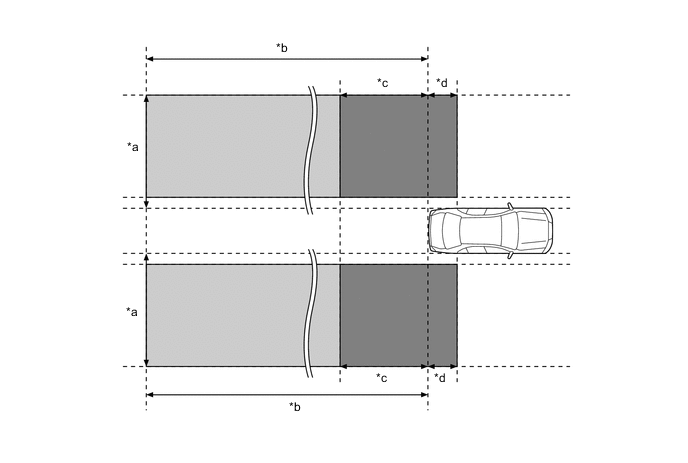
*a Approximately 3.5 m (11.5 ft) *b Approximately 60 m (197 ft) *c Approximately 3.0 m (9.8 ft) *d Approximately 1.0 m (3.3 ft) 
Detection Area (for Vehicle in Blind Spot) 
Detection Area (for Rapidly Approaching Vehicle from Behind) Tech Tips
If another vehicle that is rapidly approaching the vehicle's blind spot is detected, the notification timing is determined by the relative speed of the approaching vehicle. The notification timing for vehicles rapidly approaching the vehicle's blind spot can be customized. For details, refer to the Repair Manual.
-
Detection Area (for Vehicle in Blind Spot)
-
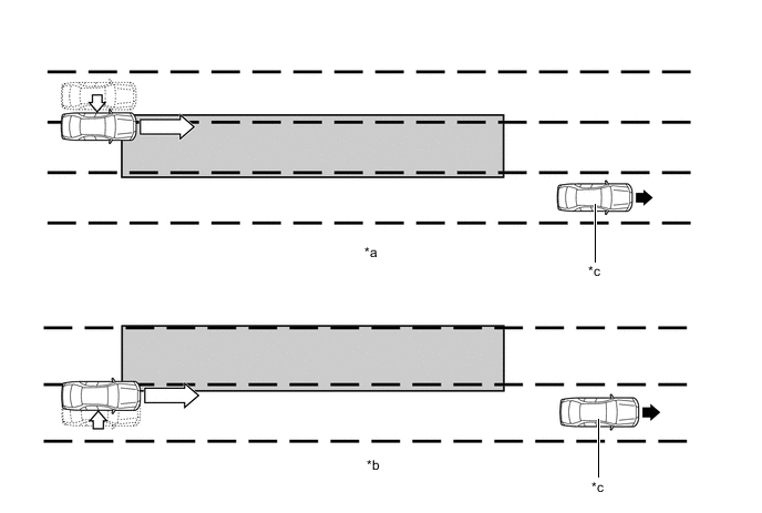
When this vehicle is overtaken by another vehicle in an adjacent lane.
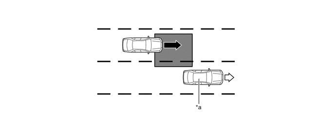
*a This Vehicle - - 
Vehicle Speed (Fast) 
Vehicle Speed (Slow) Detection Area - - -
When another vehicle enters the detection area of this vehicle due to a lane change.
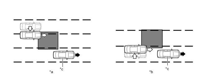
*a Other vehicle enters the detection area during lane change (merge in) (Type 1). *b Other vehicle enters the detection area during lane change (merge in) (Type 2). *c This Vehicle - - Motion direction of this vehicle Motion direction of other vehicle Detection Area - -
-
-
Detection Area (for Rapidly Approaching Vehicle from Behind)
-
When another vehicle is rapidly approaching from behind.
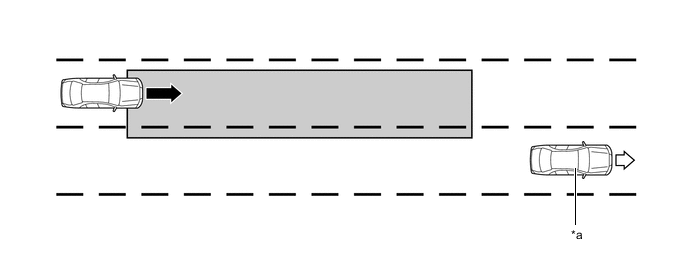
*a This Vehicle - - Vehicle Speed (Fast) Vehicle Speed (Slow) Detection Area - - -
When another vehicle enters the detection area of this vehicle due to a lane change and approaches this vehicle.
*a Other vehicle enters the detection area during lane change (merge in) (Type 1). *b Other vehicle enters the detection area during lane change (merge in) (Type 2). *c This Vehicle - - Motion direction of this vehicle Motion direction of other vehicle Detection Area - -
-
-
-
The RCTA function operates when all of the following conditions are met:
-
The RCTA function is on.
-
The shift lever is in R.
-
The speed of this vehicle is less than approximately 8 km/h (5 mph).
-
Target vehicle's speed is between approximately 8 km/h (5 mph) and 28 km/h (18 mph).
-
-
The RCTA function can detect vehicles in its detection areas.
-
The system continuously measures the relative speed of an approaching vehicle and its distance. If it is determined that the approaching vehicle will cross the path of this vehicle, the Estimated Crossing Time (ECT) is calculated. When the ECT is 2.5 seconds or less, the system alerts the driver by flashing the outer rear view mirror indicator lights and sounding the RCTA buzzer (blind spot monitor buzzer).
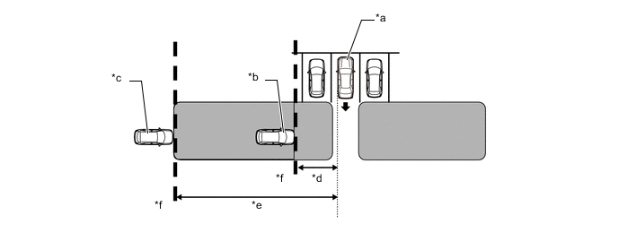
*a This Vehicle *b Target Vehicle (Approximately 8 km/h (5 mph)) *c Target Vehicle (Approximately 28 km/h (18 mph)) *d Approximately 5.5 m (18.0 ft.) *e Approximately 20 m (66 ft.) *f Target Detection Line Alert Area - - -
Normal Parking
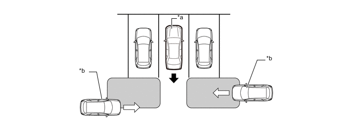
*a This Vehicle *b Target Vehicle Alert Area - -
-
-
According to operation conditions, the blind spot monitor function promotes safety confirmation by using the outer rear view mirror indicator light to inform the driver that system detects vehicles that are in or rapidly approaching the vehicle's blind spot.
-
The outer rear view mirror indicator light illuminates when a vehicle is in or rapidly approaching the vehicle's blind spot and the turn light switch is not operated. The indicator light flashes when a vehicle is in or rapidly approaching the vehicle's blind spot and the turn light switch is operated.
-
According to operation conditions, the RCTA function promotes safety confirmation by using the outer rear view mirror indicator lights and RCTA buzzer (blind spot monitor buzzer) to inform the driver that another vehicle has entered the blind spot monitor sensor alert area of this vehicle.
-
When this vehicle is reversing, if a vehicle enters the detection area of the blind spot monitor sensors and it is determined the vehicle will cross the path of this vehicle, the system alerts the driver by flashing the outer rear view mirror indicator lights and sounding the RCTA buzzer (blind spot monitor buzzer).
-
-
DIAGNOSIS
-
The blind spot monitor system is equipped with a diagnosis function that can display warning messages in the multi-information display. For details, refer to the Repair Manual.
-