FRONT BUMPER(except Sport Package) REASSEMBLY
CAUTION / NOTICE / HINT
PROCEDURE
-
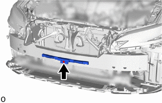
INSTALL FRONT BUMPER NO. 2 REINFORCEMENT SUB-ASSEMBLY
-
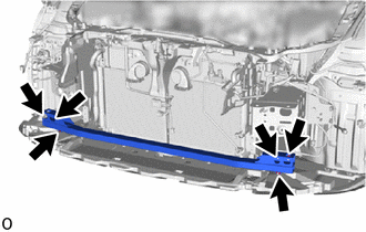
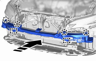
Install the front bumper No. 2 reinforcement sub-assembly with the 6 nuts.
- Torque:
- 25 N*m { 255 kgf*cm, 18 ft.*lbf }
-
-
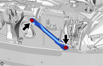
INSTALL FRONT BUMPER REINFORCEMENT SUB-ASSEMBLY
-
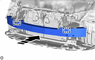

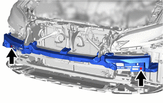
Install in this Direction Align the positions of the guide on the vehicle and front bumper reinforcement sub-assembly, and set it as shown in the illustration.
-
Install the front bumper reinforcement sub-assembly with the 8 bolts.
- Torque:
- 38 N*m { 387 kgf*cm, 28 ft.*lbf }
-
-
INSTALL HEADLIGHT ASSEMBLY LH
-
INSTALL HEADLIGHT ASSEMBLY RH
Tech Tips
Use the same procedure described for the LH side.
-
INSTALL FRONT BUMPER SIDE RETAINER LH
-
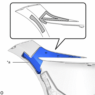
Install in this Direction Attach the clip to install the front bumper side retainer LH as shown in the illustration.
-
Install the bolt.
-
-
INSTALL FRONT BUMPER SIDE RETAINER RH
Tech Tips
Use the same procedure described for the LH side.
-
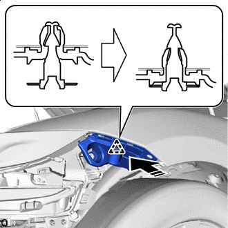
INSTALL LOWER ARM BRACKET BRACE SUB-ASSEMBLY LH
-
Install the lower arm bracket brace sub-assembly LH with the 2 bolts.
- Torque:
- 20 N*m { 204 kgf*cm, 15 ft.*lbf }
-
-
INSTALL LOWER ARM BRACKET BRACE SUB-ASSEMBLY RH
Tech Tips
Use the same procedure described for the LH side.
-
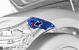
INSTALL FRONT BUMPER NO. 2 ENERGY ABSORBER
-
Install the front bumper No. 2 energy absorber with the bolt.
- Torque:
- 7.5 N*m { 76 kgf*cm, 66 in.*lbf }
-
-
INSTALL FRONT BUMPER ENERGY ABSORBER SUB-ASSEMBLY
-
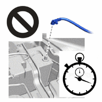
Check that the engine switch off.
-
Check that the cable is disconnected from the negative (-) battery terminal.
CAUTION:
Wait at least 90 seconds after disconnecting the cable from the negative (-) battery terminal to disable the SRS system.
-
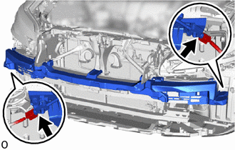
Install in this Direction Attach the guide and claw to install the front bumper energy absorber sub-assembly as shown in the illustration.
-
Install the 2 bolts.
- Torque:
- 7.5 N*m { 76 kgf*cm, 66 in.*lbf }
-
Connect the 2 connectors of the pedestrian detection chamber assembly.
Note
When connecting any pedestrian detection chamber assembly connector, take care not to damage the pedestrian detection chamber assembly wire harness.
-
Before connecting the connector, check that the position of the housing lock is correct as shown in the illustration.
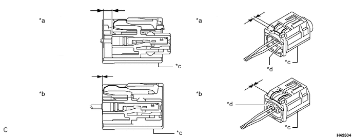
*a Correct *b Incorrect *c CPA *d Housing -
While holding the CPA be sure to engage the connectors until they are locked and check that the CPA is in its original position (when locking, make sure that a click sound can be heard).
Note
Do not push down the upper part of the CPA shown in the illustration when connecting the airbag connector.
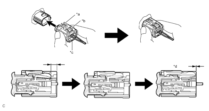
*a CPA Upper Part *b Housing Lock *c CPA *d Connection is Completed
-
-
-
INSTALL NO. 1 MOULDING TAPE
Tech Tips
-
When installing the No. 1 moulding tape, heat the front bumper cover.
-
Use the same procedure for the RH and LH side.
Standard Item Temperature Front Bumper Cover 20 to 30°C (68 to 86°F)
-
Clean the No. 1 moulding tape installation surface with a non-residue solvent.
-
Remove the peeling paper on a new No. 1 moulding tape while making sure not to touch the adhesional surface.
-
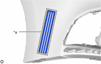
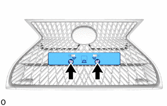
*a Mark-off Line Install the No. 1 moulding tape in the position shown in the illustration.
Tech Tips
Press the No. 1 moulding tape firmly to install it.
-
Remove the application sheet.
-
-
INSTALL LOWER RADIATOR GRILLE MOULDING
-
Install in this Direction Attach the claw to install the lower radiator grille moulding as shown in the illustration.
-
Install the screw.
-
-
INSTALL UPPER RADIATOR SEAL
Tech Tips
When installing the upper radiator seal, heat the radiator grille moulding.
Standard Item Temperature Radiator Grille Moulding 20 to 30°C (68 to 86°F) CAUTION:
-
Do not touch the heat light and heated parts.
-
Touching the heat light may result in burns.
-
Touching heated parts for a long time may result in burns.
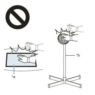
*a Heated Part *b Heat Light
-
Clean the radiator grille moulding surface.
-
Remove any remaining double-sided tape from the radiator grille moulding.
-
Wipe off any tape adhesive residue with cleaner.
Note
-
Installing the upper radiator seal with some double-sided tape remaining may cause poor adhesion. Perform this procedure until sufficiently removed it.
-
Make sure to use a cloth when removing. Using a screwdriver, etc., may cause damage and poor adhesion.
-
-
-
Apply primer to radiator grille moulding on the installation area of the upper radiator seal using a brush or felt.
Note
-
Replace the brush or felt if it is dirty or has become hardened.
-
Keep any painted surface free from primer.
-
If the primer contacts a painted surface, it may leave light primer marks. Therefore, use protective tape when using liquid primer.
-
Do not touch surfaces to which primer has been applied until the upper radiator seal has been attached.

Primer - - -
-
Let the primer dry sufficiently.
Note
Do not touch applied surfaces until the primer is dry.
Recommended drying time 10 minutes or more (at 23 °C (73 °F)) -
Remove the peeling paper of the new upper radiator seal trying not to touch the adhesional surface.
-
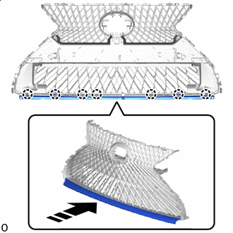
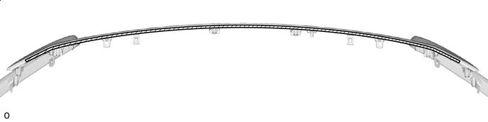
Install the upper radiator seal as shown in the illustration.
Tech Tips
Press the upper radiator seal firmly to install it.
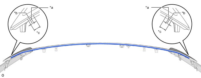
*a Mark-off Line *b 5.0 mm (0.197 in.) *c 10.0 mm (0.394 in.) - -
-
-
INSTALL RADIATOR GRILLE MOULDING
-
Install in this Direction Attach the claw to install the radiator grille moulding as shown in the illustration.
-
Install the 4 screws.
-
-
INSTALL NUT
-
Install the 2 nuts.
-
-
INSTALL RADIATOR GRILLE (OR FRONT PANEL) EMBLEM
-
Install in this Direction Attach the guide and claw to install the radiator grille (or front panel) emblem as shown in the illustration.
-
Install the 2 screws.
-
-
INSTALL FRONT BUMPER EXTENSION MOUNTING BRACKET
-
for Type A:
-
Install in this Direction Attach the claw to install the front bumper extension mounting bracket.
-
Install the 2 screws.
-
-
for Type B:
-
Install in this Direction Attach the claw to install the front bumper extension mounting bracket.
-
Install the 2 screws.
-
-
-
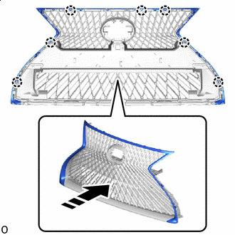
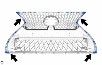
INSTALL RADIATOR GRILLE ASSEMBLY
-
Attach the guide and claw to install the radiator grille assembly as shown in the illustration.
Install in this Direction - - -
Install the 17 screws.
-
-
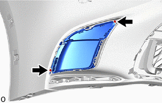
INSTALL RADIATOR GRILLE SEAL
Tech Tips
When installing the radiator grille seal, heat the radiator grille assembly.
Standard Item Temperature Radiator Grille Assembly 20 to 30°C (68 to 86°F) CAUTION:
-
Do not touch the heat light and heated parts.
-
Touching the heat light may result in burns.
-
Touching heated parts for a long time may result in burns.
*a Heated Part *b Heat Light
-
Clean the radiator grille assembly surface.
-
Remove any remaining double-sided tape from the radiator grille assembly.
-
Wipe off any tape adhesive residue with cleaner.
Note
-
Installing the radiator grille seal with some double-sided tape remaining may cause poor adhesion. Perform this procedure until sufficiently removed it.
-
Make sure to use a cloth when removing. Using a screwdriver, etc., may cause damage and poor adhesion.
-
-
-
Primer Apply primer to radiator grille assembly on the installation area of the radiator grille seal using a brush or felt.
Note
-
Replace the brush or felt if it is dirty or has become hardened.
-
Keep any painted surface free from primer.
-
If the primer contacts a painted surface, it may leave light primer marks. Therefore, use protective tape when using liquid primer.
-
Do not touch surfaces to which primer has been applied until the radiator grille seal has been attached.
-
-
Let the primer dry sufficiently.
Note
Do not touch applied surfaces until the primer is dry.
Recommended drying time 10 minutes or more (at 23 °C (73 °F)) -
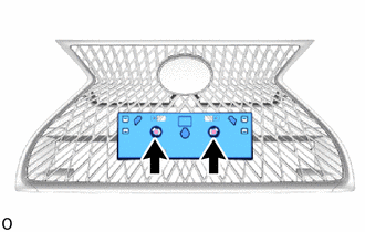
Remove the peeling paper on a new radiator grille seal while making sure not to touch the adhesional surface.
-
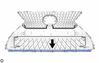
Install the radiator grille seal in the position shown in the illustration.
Note
Press the radiator grille seal firmly to install it.
-
-
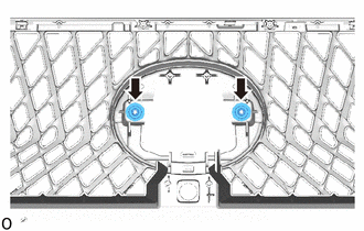
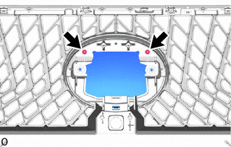
INSTALL MILLIMETER WAVE RADAR SENSOR ASSEMBLY (w/ Dynamic Radar Cruise Control System)
-
INSTALL FRONT TELEVISION CAMERA ASSEMBLY (w/ Panoramic View Monitor System)
-
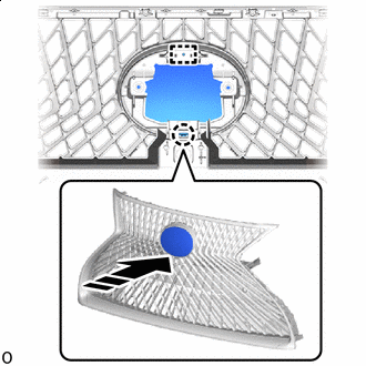
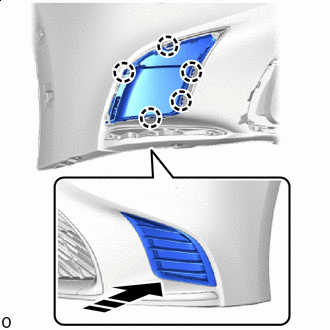
INSTALL FRONT BUMPER HOLE COVER RH
-
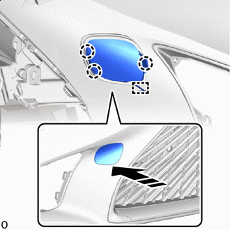
Install in this Direction Attach the anti-drop hook.
-
Attach the claw to install the front bumper hole cover RH as shown in the illustration.
-
-
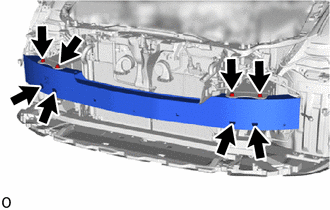
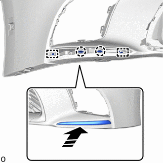
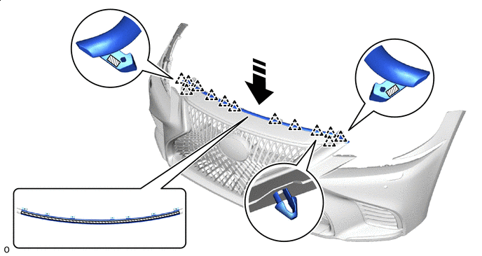
INSTALL FRONT BUMPER RETAINER
Tech Tips
When installing the front bumper retainer, heat the front bumper cover.
Standard Item Temperature Front Bumper Cover 20 to 30°C (68 to 86°F)
-
Clean the front bumper cover installation surface with a non-residue solvent.
-
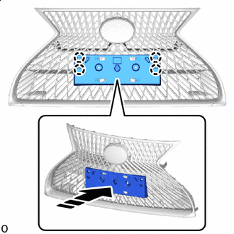
Remove the peeling paper on a new front bumper retainer while making sure not to touch the adhesional surface.
-
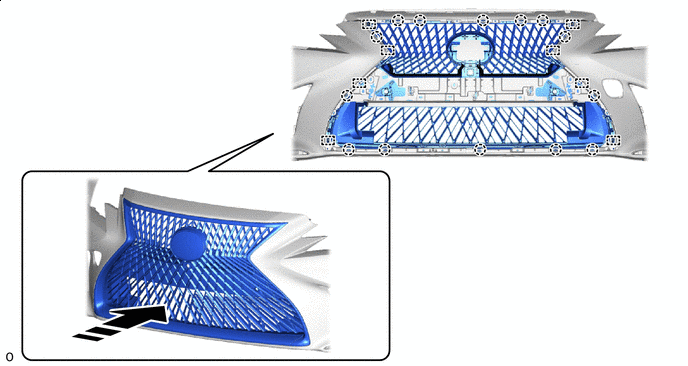
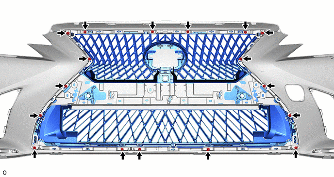
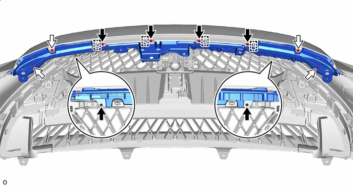
*a Mark-off Line Double-sided Tape Install the 2 front bumper retainers in the position shown in the illustration.
Note
Press the front bumper retainer firmly to install it.
-
-
INSTALL RADIATOR GRILLE SIDE MOULDING LH
-
Install in this Direction Attach the guide and claw to install the radiator grille side moulding LH as shown in the illustration.
-
Install the 2 screws.
-
-
INSTALL RADIATOR GRILLE SIDE MOULDING RH
Tech Tips
Use the same procedure described for the LH side.
-
INSTALL RADIATOR GRILLE BRACKET LH
-
Install in this Direction Attach the claw to install the radiator grille bracket LH as shown in the illustration.
-
Install the 2 screws.
-
-
INSTALL RADIATOR GRILLE BRACKET RH
Tech Tips
Use the same procedure described for the LH side.
-
INSTALL FRONT BUMPER REINFORCEMENT EXTENSION LH
-
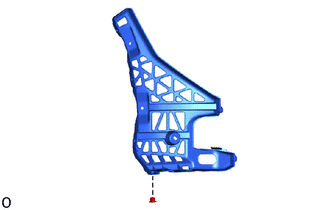
Install the grommet to the front bumper reinforcement extension LH.
-
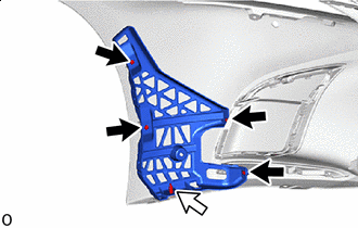

Screw 
Clip Install the front bumper reinforcement extension LH with the clip.
-
Install the 4 screws.
-
-
INSTALL FRONT BUMPER REINFORCEMENT EXTENSION RH
Tech Tips
Use the same procedure described for the LH side.
-
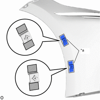
INSTALL FRONT BUMPER NO. 2 SIDE RETAINER LH
Tech Tips
When installing the front bumper No. 2 side retainer LH, heat the front bumper cover.
Standard Item Temperature Front Bumper Cover 20 to 30°C (68 to 86°F)
-
Clean the front bumper cover installation surface with a non-residue solvent.
-
Remove the peeling paper on a new front bumper No. 2 side retainer LH while making sure not to touch the adhesional surface.
-
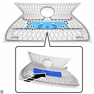
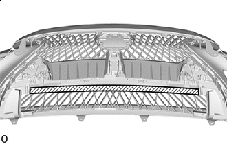
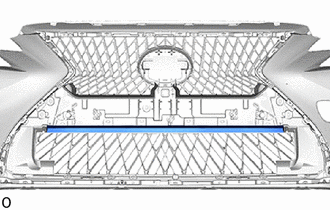
*a Mark-off Line Double-sided Tape Install the front bumper No. 2 side retainer LH in the position shown in the illustration.
Note
Press the front bumper No. 2 side retainer LH firmly to install it.
-
-
INSTALL FRONT BUMPER NO. 2 SIDE RETAINER RH
Tech Tips
Use the same procedure described for the LH side.
-
INSTALL UPPER RADIATOR GRILLE
-
Insert the guide and install the upper radiator grille.
-
Install the 4 clips.
-
Install the 6 screws.
Screw Clip
-
-
INSTALL RADIATOR GRILLE PROTECTOR
Tech Tips
When installing the radiator grille protector, heat the front bumper cover.
Standard Item Temperature Front Bumper Cover 20 to 30°C (68 to 86°F) CAUTION:
-
Do not touch the heat light and heated parts.
-
Touching the heat light may result in burns.
-
Touching heated parts for a long time may result in burns.
*a Heated Part *b Heat Light
-
Clean the front bumper cover surface.
-
Remove the double-sided tape from the front bumper cover.
-
Wipe off any tape adhesive residue with cleaner.
Note
-
Installing the front bumper cover with some double-sided tape remaining may cause poor adhesion. Perform this procedure until sufficiently removed it.
-
Make sure to use a cloth when removing. Using a screwdriver, etc., may cause damage and poor adhesion.
-
-
-
Apply primer to front bumper cover on the installation area of the radiator grille protector using a brush or felt.
Note
-
Replace the brush or felt if it is dirty or has become hardened.
-
Keep any painted surface free from primer.
-
If the primer contacts a painted surface, it may leave light primer marks. Therefore, use protective tape when using liquid primer.
-
Do not touch surfaces to which primer has been applied until the radiator grille protector has been attached.
-
-
Let the primer dry sufficiently.
Note
Do not touch applied surfaces until the primer is dry.
Recommended drying time 10 minutes or more (at 23 °C (73 °F)) -
Remove the peeling paper on a new radiator grille protector while making sure not to touch the adhesional surface.
-
Attach the clip and install the radiator grille protector as shown in the illustration.
Note
Press the radiator grille protector firmly to install it.
Install in this Direction Double-sided Tape
-
-
INSTALL FRONT ULTRASONIC SENSOR CLIP
-
INSTALL FRONT CENTER ULTRASONIC SENSOR
-
INSTALL FRONT CORNER ULTRASONIC SENSOR RETAINER
-
INSTALL FRONT CORNER ULTRASONIC SENSOR
-
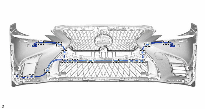
INSTALL NO. 4 ENGINE ROOM WIRE
-
Attach the clamp to install the No. 4 engine room wire.
-
Connect each connector.
Note
Do not apply excessive loads to the retainer. Otherwise, it may peel off.
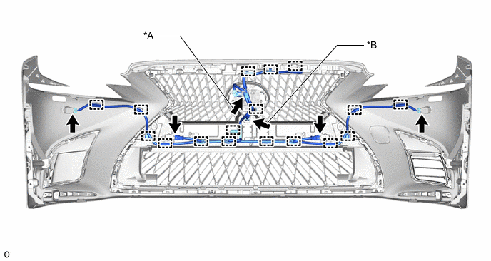
*A w/ Dynamic Radar Cruise Control System *B w/ Panoramic View Monitor System
-
-
INSTALL NO. 1 HEADLIGHT CLEANER HOSE
-
Attach the clamp to install the No. 1 headlight cleaner hose.
-
-
INSTALL NO. 2 WASHER BRACKET
-
INSTALL WASHER BRACKET
Tech Tips
Use the same procedure described for the No. 2 washer bracket.
-
INSTALL HEADLIGHT WASHER ACTUATOR SUB-ASSEMBLY LH
-
INSTALL HEADLIGHT WASHER ACTUATOR SUB-ASSEMBLY RH
Tech Tips
Use the same procedure described for the LH side.
-
INSTALL HEADLIGHT WASHER COVER LH
-
INSTALL HEADLIGHT WASHER COVER RH
Tech Tips
Use the same procedure described for the LH side.