EMISSION CONTROL SYSTEM(except Korea)
Figure 1. Evaporative Emission Control System
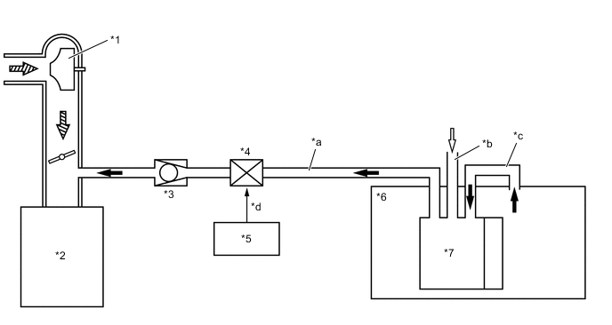
| *1 | Turbocharger Sub-Assembly
|
*2 | Engine |
| *3 | No. 1 Check Valve | *4 | Purge Vacuum Switching Valve (VSV) |
| *5 | ECM | *6 | Fuel Tank Assembly |
| *7 | Charcoal Canister Sub-assembly | - | - |
| *a | Purge Line | *b | Fresh Air Line |
| *c | EVAP Line | *d | Duty Cycle Signal |
 |
Fuel Vapor |  |
Fresh Air |
 |
Intake Air | - | - |
Figure 2. Gasoline Particulate Filter (GPF) System
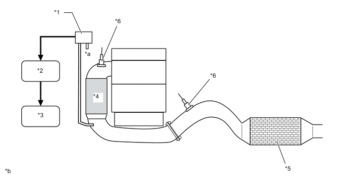
| *1 | Differential Pressure Sensor | *2 | ECM |
| *3 | Combination Meter Assembly | *4 | TWC |
| *5 | GPF | *6 | Air Fuel Ratio Sensor |
| *a | Atmosphere | *b | The illustration is a representative example. |