AIR CONDITIONING SYSTEM(for Automatic Air Conditioning System) TERMINALS OF ECU
CHECK AIR CONDITIONING AMPLIFIER ASSEMBLY
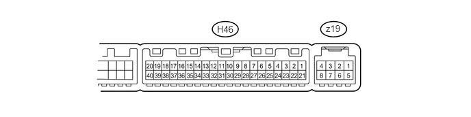
Disconnect the H46 air conditioning amplifier connector.
Measure the voltage and resistance according to the value(s) in the table below.
Terminal No. (Symbol)
Wiring Color
Terminal Description
Condition
Specified Condition
H46-1 (IG+) - H46-14 (GND)
Y - W-B
Ignition power supply
Ignition switch ON
11 to 14 V
Ignition switch off
Below 1 V
H46-21 (B) - H46-14 (GND)
W - W-B
Battery power source
Always
11 to 14 V
H46-14 (GND) - Body ground
W-B - Body ground
Ground for main power supply
Always
Below 1 Ω
If the result is not as specified, there may be a malfunction on the wire harness side.
Reconnect the H46 air conditioning amplifier connector.
Measure the voltage and resistance according to the value(s) in the table below.
Terminal No. (Symbol)
Wiring Color
Terminal Description
Condition
Specified Condition
z19-2 (BUS G) - Body ground
-
Ground for BUS IC
Always
Below 1 Ω
H46-22 (BLW) - H46-14 (GND)
R - W-B
Blower motor control signal
Ignition switch ON
Blower switch LO
Pulse generation
(see waveform 1)
H46-10 (S5-3) - H46-13 (SG-2)
B - G
Power supply for air conditioning pressure sensor
Ignition switch ON
4.75 to 5.25 V
H46-9 (PRE) - H46-13 (SG-2)
L - G
Air conditioning pressure sensor signal
Ignition switch ON
Refrigerant pressure normal (less than 3.025 MPa [30.9 kgf/cm2, 438.6 psi] and more than 0.176 MPa [1.8 kgf/cm2, 25.5 psi])
0.70 to 4.69 V
Ignition switch ON
Refrigerant pressure abnormal (less than 0.176 MPa [1.8 kgf/cm2, 25.5 psi])
Below 0.70 V
Ignition switch ON
Refrigerant pressure abnormal (more than 3.025 MPa [30.9 kgf/cm2, 438.6 psi])
4.69 V or higher
H46-30 (S5-1) - H46-14 (GND)
LG - W-B
Cooler thermistor (solar sensor) power source
Ignition switch ON
4.5 to 5.5 V
H46-33 (TSD) - H46-14 (GND)
L - W-B
Cooler thermistor (solar sensor) power signal (for driver side)
Ignition switch ON
Solar sensor subjected to electric light
Vehicle indoors
0.8 to 4.3 V
Ignition switch ON
Solar sensor covered with cloth
Vehicle indoors
Below 0.8 V
H46-32 (TSP) - H46-14 (GND)
P - W-B
Cooler thermistor (solar sensor) power signal (for front passenger side)
Ignition switch ON
Solar sensor subjected to electric light
Vehicle indoors
0.8 to 4.3 V
Ignition switch ON
Solar sensor covered with cloth
Vehicle indoors
Below 0.8 V
H46-29 (TR) - H46-34 (SG-1)
GR - V
Room temperature sensor signal
Ignition switch ON
Cabin temperature at 25°C (77°F)
1.8 to 2.2 V
Ignition switch ON
Cabin temperature at 40°C (104°F)
1.2 to 1.6 V
H46-2 (SOL+) - H46-14 (GND)
LG - W-B
Compressor with pulley assembly operation signal
Engine running
A/C switch on
Blower switch LO
Pulse generation
(see waveform 2)
H46-40 (PTC1) - Body ground*1
W - Body ground
HTR SUB NO.1 relay operation signal
Engine running (1250 rpm or more)
Temperature setting MAX HOT
Outside temperature 10°C (50°F) or less
Engine coolant temperature 75°C (167°F) or less
Headlight dimmer switch off
Blower switch off → on (after 30 seconds)
11 to 14 V → Below 1 V*2
H46-3 (PTC2) - Body ground*1
B - Body ground
HTR SUB NO.2 relay operation signal
Engine running (1250 rpm or more)
Temperature setting MAX HOT
Outside temperature 10°C (50°F) or less
Engine coolant temperature 70°C (158°F) or less
Headlight dimmer switch off
Blower switch off → on (after 30 seconds)
11 to 14 V → Below 1 V*2
H46-39 (PTC3) - Body ground*1
BR - Body ground
HTR SUB NO.3 relay operation signal
Engine running (1250 rpm or more)
Temperature setting MAX HOT
Outside temperature 10°C (50°F) or less
Engine coolant temperature 65°C (149°F) or less
Headlight dimmer switch off
Blower switch off → on (after 30 seconds)
11 to 14 V → Below 1 V*2
H46-27 (HLS)*1 - H46-14 (GND)
BE - W-B
Headlight signal (PTC heater control)
Engine started
Headlight dimmer switch off
11 to 14 V
Engine started
Headlight dimmer switch on
Below 1 V
z19-5 (SGA) - Body ground
-
Ground for evaporator temperature sensor
Always
Below 1 Ω
z19-6 (TEA) - z19-5 (SGA)
-
Evaporator temperature sensor signal
Ignition switch ON
Evaporator temperature at 0°C (32°F)
1.7 to 2.1 V
Ignition switch ON
Evaporator temperature at 15°C (59°F)
0.9 to 1.3 V
z19-3 (BUS) - z19-2 (BUS G)
-
BUS IC control signal
Ignition switch ON
Pulse generation
z19-4 (B BUS) - z19-2 (BUS G)
-
Power supply for BUS IC
Always
11 to 14 V
*1: w/ PTC Heater
Tip:*2: After the measurement conditions are met, wait 30 seconds before performing measurements.
If the result is not as specified, the air conditioning amplifier assembly may have a malfunction.
-
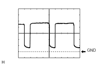
Using an oscilloscope, check waveform 1.
Table 1. Blower Motor Control Signal Item
Content
Terminal No. (Symbol)
H46-22 (BLW) - H46-14 (GND)
Tool Setting
1 V/DIV., 500 μs/DIV.
Condition
Ignition switch ON
Blower switch LO
Tip:When the blower level is increased, the duty ratio changes accordingly.
-
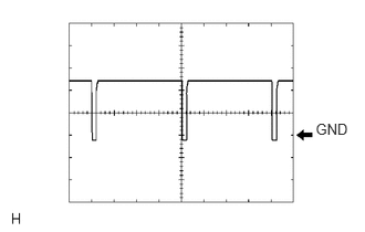
Using an oscilloscope, check waveform 2.
Table 2. Compressor with Pulley Operation Signal Item
Content
Terminal No. (Symbol)
H46-2 (SOL+) - H46-14 (GND)
Tool Setting
5 V/DIV., 500 μs/DIV.
Condition
Engine running
A/C switch on
Blower switch LO
CHECK AIR CONDITIONING CONTROL ASSEMBLY

Disconnect the H21 control connector.
Measure the resistance and voltage according to the value(s) in the table below.
Terminal No. (Symbol)
Wiring Color
Terminal Description
Condition
Specified Condition
H21-2 (IG+) - H21-5 (GND)
R - BR
Ignition power supply
Ignition switch ON
11 to 14 V
Ignition switch off
Below 1 V
H21-5 (GND) - Body ground
BR - Body ground
Ground
Always
Below 1 Ω
If the result is not as specified, there may be a malfunction on the wire harness side.
CHECK MAIN BODY ECU (INSTRUMENT PANEL JUNCTION BLOCK ASSEMBLY)
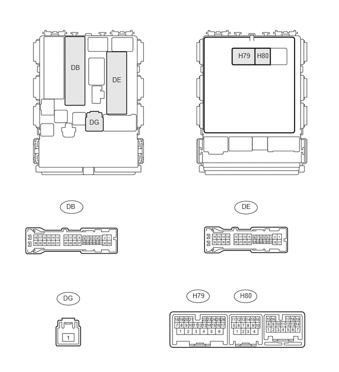
Disconnect the DB, DE, DG and H80 ECU connectors.
Measure the voltage and resistance according to the value(s) in the table below.
Terminal No. (Symbol)
Wiring Color
Terminal Description
Condition
Specified Condition
DE-28 (GND1) - Body ground
W-B - Body ground
Ground
Always
Below 1 Ω
H80-4 (GND2) - Body ground
W-B - Body ground
Ground
Always
Below 1 Ω
DB-30 (BECU) - Body ground
W - Body ground
Power source
Always
11 to 14 V
DG-1 (ALTB) - Body ground
W - Body ground
Power source
Always
11 to 14 V
If the result is not as specified, there may be a malfunction on the wire harness side.
Reconnect the DB, DE, DG and H80 ECU connectors.
Measure the voltage according to the value(s) in the table below.
Terminal No. (Symbol)
Wiring Color
Terminal Description
Condition
Specified Condition
H79-20 (HRLY) - DE-28 (GND1)*
B - W-B
H-LP relay drive output
Headlight dimmer switch in head position
Below 1 V
Headlight dimmer switch not in head position
11 to 14 V
*: w/ PTC Heater
If the result is not as specified, the main body ECU (instrument panel junction block assembly) may have a malfunction.