SFI SYSTEM(w/ Canister Pump Module), Diagnostic DTC:P24D51F, P2B7A1F
| DTC Code | DTC Name |
|---|---|
| P24D51F | EVAP System Pressure Sensor/Switch "B" Circuit Intermittent Circuit Intermittent |
| P2B7A1F | EVAP System Pressure Sensor/Switch "C" Circuit Intermittent Circuit Intermittent |
DESCRIPTION
Refer to DTC P143E9C.
| DTC No. | Detection Item | DTC Detection Condition | Trouble Area | MIL | Memory | Note |
|---|---|---|---|---|---|---|
| P24D51F | EVAP System Pressure Sensor/Switch "B" Circuit Intermittent Circuit Intermittent | Both of the following conditions (a) and (b) are met for 10 seconds or more (2 trip detection logic): (a) The purge VSV operation duty signal is 0%. (b) The amplitude of the No. 2 turbo pressure sensor (bank 1) output voltage is at the threshold or higher. |
|
Comes on | DTC stored | SAE: P24D9 |
| P2B7A1F | EVAP System Pressure Sensor/Switch "C" Circuit Intermittent Circuit Intermittent | Both of the following conditions (a) and (b) are met for 10 seconds or more (2 trip detection logic): (a) The purge VSV operation duty signal is 0%. (b) The amplitude of the No. 2 turbo pressure sensor (bank 2) output voltage is at the threshold or higher. |
|
Comes on | DTC stored | SAE: P2B7E |
MONITOR DESCRIPTION
During fuel cut, the No. 2 turbo pressure sensor output voltage stabilizes because the purge VSV is stopped.
When the amplitude of the No. 2 turbo pressure sensor output voltage is at the threshold or higher during fuel cut, a malfunction in the No. 2 turbo pressure sensor is judged, and the ECM illuminates the MIL and stores a DTC.
MONITOR STRATEGY
| Required Sensors/Components (Main) | No. 2 turbo pressure sensor |
| Required Sensors/Components (Related) | Mass air flow meter sub-assembly Purge VSV Engine coolant temperature sensor |
| Frequency of Operation | Continuous |
CONFIRMATION DRIVING PATTERN
-
Connect the GTS to the DLC3.
-
Turn the engine switch on (IG).
-
Turn the GTS on.
-
Clear the DTCs (even if no DTCs are stored, perform the clear DTC procedure).
-
Turn the engine switch off and wait for at least 30 seconds.
-
Turn the engine switch on (IG).
-
Turn the GTS on.
-
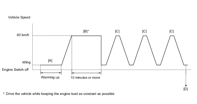
Start the engine and warm it up until the engine coolant temperature is 75°C (167°F) or higher [A].
-
Drive the vehicle at approximately 60 km/h (37 mph) for 10 minutes or more [B].
CAUTION:
When performing the confirmation driving pattern, obey all speed limits and traffic laws.
Tech Tips
Drive the vehicle while keeping the engine load as constant as possible.
-
Using the GTS, enter the following menus to check the fuel-cut status: Powertrain / Engine / Data List / Idle Fuel Cut.
-
With the shift state M selected, drive the vehicle at 60 km/h (37 mph), and then decelerate the vehicle by releasing the accelerator pedal for 10 seconds or more to perform the fuel-cut [C].
CAUTION:
When performing the confirmation driving pattern, obey all speed limits and traffic laws.
Tech Tips
While "Idle Fuel Cut" on the Data List is ON, fuel-cut control is being executed.
-
Repeat step [C] 2 times or more in one driving cycle.
-
Enter the following menus: Powertrain / Engine / Trouble Codes / Pending [D].
-
Read the pending DTCs.
Tech Tips
-
If a pending DTC is output, the system is malfunctioning.
-
If a pending DTC is not output, perform the following procedure.
-
-
Enter the following menus: Powertrain / Engine / Utility / All Readiness.
-
Input the DTC: P24D51F or P2B7A1F.
-
Check the DTC judgment result.
GTS Display Description NORMAL
-
DTC judgment completed
-
System normal
ABNORMAL
-
DTC judgment completed
-
System abnormal
INCOMPLETE
-
DTC judgment not completed
-
Perform driving pattern after confirming DTC enabling conditions
Tech Tips
-
If the judgment result is NORMAL, the system is normal.
-
If the judgment result is ABNORMAL, the system is malfunctioning.
-
If the judgment result is INCOMPLETE, drive the vehicle with the shift state M, and then perform step [C] again.
-
CAUTION / NOTICE / HINT
Tech Tips
-
Read Freeze Frame Data using the GTS. The ECM records vehicle and driving condition information as Freeze Frame Data the moment a DTC is stored. When troubleshooting, Freeze Frame Data can help determine if the vehicle was moving or stationary, if the engine was warmed up or not, if the air fuel ratio was lean or rich, and other data from the time the malfunction occurred.
-
Bank 1 refers to the bank that includes the No. 1 cylinder*.
*: The No. 1 cylinder is the cylinder which is farthest from the transmission.
-
Bank 2 refers to the bank that does not include the No. 1 cylinder.
DTC Suspected Area P24D51F Bank 1 P2B7A1F Bank 2
PROCEDURE
-
CHECK ANY OTHER DTCS OUTPUT (IN ADDITION TO DTC P24D51F OR P2B7A1F)
-
Connect the GTS to the DLC3.
-
Turn the engine switch on (IG).
-
Turn the GTS on.
-
Enter the following menus: Powertrain / Engine / Trouble Codes.
-
Read the DTCs.
Powertrain > Engine > Trouble CodesResult Result Proceed to DTC P24D51F or P2B7A1F is output A DTC P24D51F or P2B7A1F and other DTCs are output B Tech Tips
If any DTCs other than P24D51F or P2B7A1F are output, troubleshoot those DTCs first.
B 
GO TO DTC CHART Click here
A 
-
-
CLEAR DTC
-
Connect the GTS to the DLC3.
-
Turn the engine switch on (IG).
-
Turn the GTS on.
-
Clear the DTCs.
Powertrain > Engine > Clear DTCs -
Turn the engine switch off and wait for at least 30 seconds.
Result Proceed to NEXT
NEXT
-
-
READ VALUE USING GTS (PURGE PRESSURE SENSOR BANK1, PURGE PRESSURE SENSOR BANK2)
-
Connect the GTS to the DLC3.
-
Turn the engine switch on (IG).
-
Turn the GTS on.
-
Enter the following menus: Powertrain / Engine / Data List / Purge Pressure Sensor Bank1, Purge Pressure Sensor Bank2.
Powertrain > Engine > Data ListTester Display Purge Pressure Sensor Bank1 Purge Pressure Sensor Bank2 -
Read the values displayed on the GTS while wiggling the ECM wire harness.
Result Result Proceed to Other than below A Value in Data List changes when wire harness is wiggled B
B 
REPAIR OR REPLACE HARNESS OR CONNECTOR (NO. 2 TURBO PRESSURE SENSOR - ECM) Click here
A
-
-
REPLACE NO. 2 TURBO PRESSURE SENSOR
-
Replace the No. 2 turbo pressure sensor.
Result Proceed to NEXT
NEXT
-
-
CLEAR DTC
-
Connect the GTS to the DLC3.
-
Turn the engine switch on (IG).
-
Turn the GTS on.
-
Clear the DTCs.
Powertrain > Engine > Clear DTCs -
Turn the engine switch off and wait for at least 30 seconds.
Result Proceed to NEXT
NEXT
-
-
CHECK WHETHER DTC OUTPUT RECURS (DTC P24D51F OR P2B7A1F)
-
Drive the vehicle in accordance with the driving pattern described in Confirmation Driving Pattern.
-
Enter the following menus: Powertrain / Engine / Trouble Codes.
-
Read the DTCs.
Powertrain > Engine > Trouble CodesResult Result Proceed to DTCs are not output A DTC P24D51F or P2B7A1F is output B
A
END
B
REPLACE ECM Click here
-
-
REPAIR OR REPLACE HARNESS OR CONNECTOR (NO. 2 TURBO PRESSURE SENSOR - ECM)
-
As the DTC was stored due to a change in the contact resistance of the connector, repair or replace the wire harness or connector.
Result Proceed to NEXT
NEXT
END
-