AIR CONDITIONING PANEL(for Manual Air Conditioning System) INSPECTION
PROCEDURE
INSPECT NO. 1 HEATER CONTROL SUB-ASSEMBLY
Measure the resistance.
-
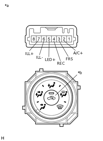
*a
Component without harness connected
(No. 1 Heater Control Sub-assembly)
*b
Recirculation/fresh Switch
Remove the No. 1 heater control sub-assembly.
Measure the resistance according to the value(s) in the table below.
Standard Resistance
Tester Connection
Condition
Specified Condition
3 (FRS) - 4 (REC)
Recirculation/fresh switch: OFF
Below 1 Ω
3 (FRS) - 4 (REC)
Recirculation/fresh switch: ON
10 kΩ or higher
5 (LED+) - 4 (REC)
Recirculation/fresh switch: OFF
10 kΩ or higher
5 (LED+) - 4 (REC)
Recirculation/fresh switch: ON
Below 1 Ω
If the result is not as specified, replace the No. 1 heater control sub-assembly.
-
Check the indicator light.
Turn the recirculation/fresh switch to the on position.
Connect a positive (+) lead from the battery to terminal 2 (A/C+) and negative (-) lead to terminal 4 (REC), and check that the indicator light comes on.
OK
The indicator light comes on.
If the result is not as specified, replace the No. 1 heater control sub-assembly.
Check that the illumination light.
Connect a positive (+) lead from the battery to terminal 7 (ILL+) and negative (-) lead to terminal 6 (ILL-), and check that the illumination light.
OK
The illumination light comes on.
If the result is not as specified, replace the bulb.
INSPECT NO. 2 HEATER CONTROL SUB-ASSEMBLY
Measure the resistance.
-
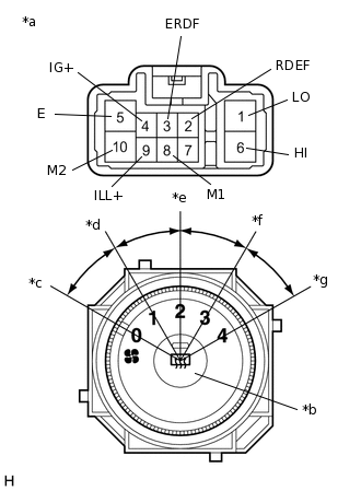
*a
Component without harness connected
(No. 2 Heater Control Sub-assembly)
*b
Rear Window Defogger Switch
*1
Blower Switch OFF Position
*2
Blower Switch LO Position
*3
Blower Switch M1 Position
*4
Blower Switch M2 Position
*5
Blower Switch HI Position
Remove the No. 2 heater control sub-assembly.
Measure the resistance according to the value(s) in the table below.
Standard Resistance
Tester Connection
Condition
Specified Condition
1 (LO), 6 (HI), 8 (M1), 10 (M2) - 5 (E)
Blower switch: OFF
10 kΩ or higher
1 (LO) - 5 (E)
Blower switch: LO
Below 1 Ω
1 (LO), 8 (M1) - 5 (E)
Blower switch: LO - M1
Below 1 Ω
1 (LO), 8 (M1) - 5 (E)
Blower switch: M1
Below 1 Ω
1 (LO), 8 (M1), 10 (M2) - 5 (E)
Blower switch: M1 - M2
Below 1 Ω
1 (LO), 10 (M2) - 5 (E)
Blower switch: M2
Below 1 Ω
1 (LO), 10 (M2), 6 (HI) - 5 (E)
Blower switch: M2 - HI
Below 1 Ω
1 (LO), 6 (HI) - 5 (E)
Blower switch: HI
Below 1 Ω
2 (RDEF) - 5 (E)
Rear window defogger switch: OFF
10 kΩ or higher
2 (RDEF) - 5 (E)
Rear window defogger switch: ON
Below 1 Ω
If the result is not as specified, replace the No. 2 heater control sub-assembly.
-
Check that the rear window defogger switch indicator light.
Connect a positive (+) lead from the battery to terminal 4 (IG+) and the negative (-) lead to terminal 5 (E).
Push the rear window defogger switch in and check that the indicator light.
OK
The indicator light comes on.
If the result is not as specified, replace the No. 2 heater control sub-assembly.
Check that the illumination light.
Connect a positive (+) lead from the battery to terminal 9 (ILL+) and negative (-) lead to terminal 7 (ILL-), and check that the illumination light.
OK
The illumination light comes on.
If the result is not as specified, replace the bulb.
INSPECT NO. 3 HEATER CONTROL SUB-ASSEMBLY
Measure the resistance.
-
*A
w/ PTC Heater
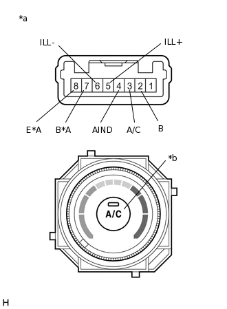
*a
Component without harness connected
(No. 3 Heater Control Sub-assembly)
*b
A/C Switch
Remove the No. 3 heater control sub-assembly.
Measure the resistance according to the value(s) in the table below.
Standard Resistance
Tester Connection
Condition
Specified Condition
2 (B) - 3 (A/C)
A/C switch: On
Below 1 Ω
2 (B) - 3 (A/C)
A/C switch: Off
10 kΩ or higher
7 (B) - 8 (E)*1
MAX HOT switch: On
Below 1 Ω
7 (B) - 8 (E)*1
MAX HOT switch: Off
10 kΩ or higher
*1: w/ PTC heater
If the result is not as specified, replace the No. 3 heater control sub-assembly.
-
Check the indicator light.
Turn the A/C switch on position.
Connect a positive (+) lead from the battery to terminal 2 (B) and negative (-) to lead terminal 4 (AIND), and check that the indicator light comes on.
OK
The indicator light comes on.
If the result is not as specified, replace the No. 3 heater control sub-assembly.
Check that the illumination light.
Connect a positive (+) lead from the battery to terminal 5 (ILL+) and negative (-) lead to terminal 6 (ILL-), and check that the illumination light.
OK
The illumination light comes on.
If the result is not as specified, replace the bulb.