ENTRY AND START SYSTEM(for Entry Function) Room Oscillator does not Recognize Key
| DTC Code | DTC Name |
|---|---|
| Room Oscillator does not Recognize Key |
DESCRIPTION
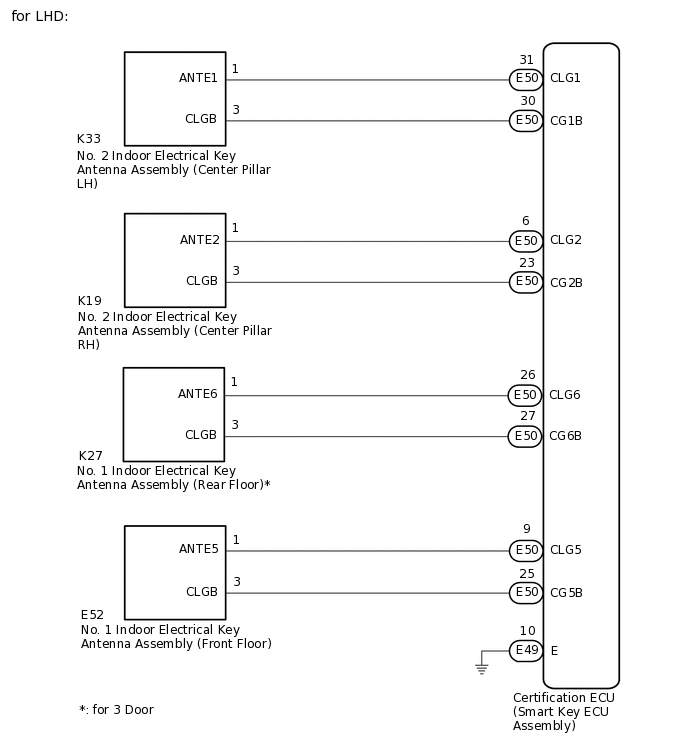
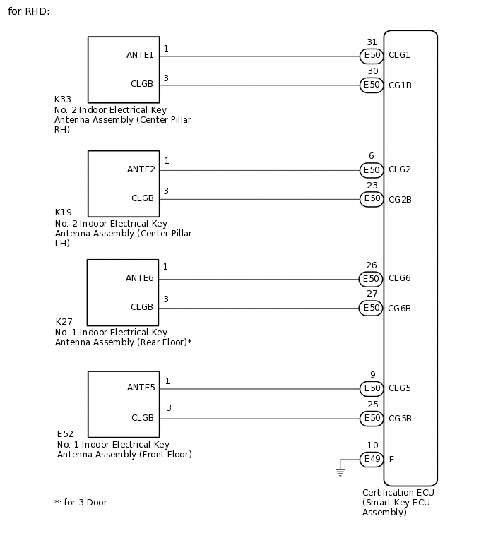
If code verification cannot be performed in the vehicle interior, there may be problems with the communication between the vehicle (indoor electrical key antenna assembly (center pillar RH), (center pillar LH) or (rear floor)*) and electrical key transmitter sub-assembly, or the certification ECU (smart key ECU assembly) may be malfunctioning. When the electrical key transmitter sub-assembly is brought into the vehicle, verification of the key ID code transmitted from the electrical key transmitter sub-assembly and the key ID code stored in the certification ECU (smart key ECU assembly) is performed. If verification cannot be performed or the codes do not match, the engine switch cannot be turned on (IG) and the engine cannot be started.
When a door is unlocked and the electrical key transmitter sub-assembly is brought into the vehicle, the certification ECU (smart key ECU assembly) activates the indoor electrical key antenna assembly which transmits radio waves to detect the electrical key transmitter sub-assembly. If the electrical key transmitter sub-assembly recognizes that it is in the detection area, it responds with the key ID code. This information is received by the indoor electrical key antenna assembly and then sent to the certification ECU (smart key ECU assembly).
*: for 3 Door
WIRING DIAGRAM
CAUTION / NOTICE / HINT
The entry and start system (for Entry Function) uses the LIN communication system and CAN communication system. Inspect the communication function by following How to Proceed with Troubleshooting. Troubleshoot the entry and start system (for Entry Function) after confirming that the communication systems are functioning properly.
When using the GTS with the engine switch off, connect the GTS to the DLC3 and turn a courtesy light switch on and off at intervals of 1.5 seconds or less until communication between the GTS and the vehicle begins. Then select Model Code "KEY REGIST" under manual mode and enter the following menus: Body Electrical / Entry&Start(CAN). While using the GTS, periodically turn a courtesy light switch on and off at intervals of 1.5 seconds or less to maintain communication between the GTS and the vehicle.
Before replacing the certification ECU (smart key ECU assembly), refer to entry and start system (for Entry Function) Precaution.
After repair, confirm that no DTCs are output by performing "DTC Output Confirmation Operation".
The indoor electrical key antenna assemblies have an antenna coil between each pair of CLG and ANTE.
PROCEDURE
CHECK ENTRY AND START SYSTEM (VEHICLE INTERIOR DETECTION)
Get into the vehicle while carrying a different, previously-registered electrical key transmitter sub-assembly.
Move the shift lever to N.*1
Depress the brake pedal*1 or clutch pedal*2.
Check that the smart warning light in the combination meter assembly illuminates (green), and then press the engine switch and check that the engine starts.
*1: for Multi-Mode Manual Transaxle
*2: for Manual Transaxle
Result
Result
Proceed to
Engine does not start
A
Engine starts normally
B
B END (ELECTRICAL KEY TRANSMITTER SUB-ASSEMBLY WAS DEFECTIVE)
CHECK WIRELESS DOOR LOCK CONTROL SYSTEM (OPERATION)
Check that the wireless door lock functions operate normally.
OK
Wireless door lock functions operate normally.
Result
Proceed to
OK
NG
CHECK ENTRY AND START SYSTEM
-
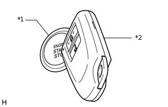
*1
Engine Switch
*2
Electrical Key Transmitter Sub-assembly
Remove the transmitter battery of the electrical key transmitter sub-assembly.
With the brake pedal*1 or clutch pedal*2 depressed, face the logo side of the electrical key transmitter sub-assembly towards the engine switch, hold the transmitter near the engine switch and then press the engine switch.
*1: for Multi-Mode Manual Transaxle
*2: for Manual Transaxle
When operating the engine switch, check whether the engine starts.
Tip:If the electrical key transmitter sub-assembly cannot be verified even though it is inside the detection area, the engine start check can be performed by removing the transmitter battery from the electrical key transmitter sub-assembly and holding the electrical key transmitter sub-assembly near the engine switch.
If the engine cannot be started when performing this inspection, the certification ECU (smart key ECU assembly), ID code box (immobiliser code ECU)* or steering lock ECU (steering lock actuator assembly) may be malfunctioning.
*: for RHD
OK
Engine starts.
Result
Proceed to
OK
NG
-
CHECK WAVE ENVIRONMENT
Install the transmitter battery to the electrical key transmitter sub-assembly.
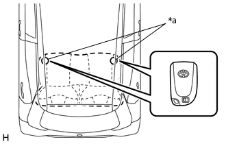
Bring the electrical key transmitter sub-assembly near the No. 2 indoor electrical key antenna assembly (center pillar RH) and perform an engine start check.
Note:Communication may not be possible if the electrical key transmitter sub-assembly is within 0.2 m (0.656 ft.) of the No. 2 indoor electrical key antenna assembly (center pillar RH).
Bring the electrical key transmitter sub-assembly near the No. 2 indoor electrical key antenna assembly (center pillar LH) and perform an engine start check.
Note:Communication may not be possible if the electrical key transmitter sub-assembly is within 0.2 m (0.656 ft.) of the No. 2 indoor electrical key antenna assembly (center pillar LH).
Bring the electrical key transmitter sub-assembly near the No. 1 indoor electrical key antenna assembly (front floor) and perform an engine start check.
Note:Communication may not be possible if the electrical key transmitter sub-assembly is within 0.2 m (0.656 ft.) of the No. 1 indoor electrical key antenna assembly (front floor).
Bring the electrical key transmitter sub-assembly near the No. 1 indoor electrical key antenna assembly (rear floor) and perform an engine start check. (for 3 Door)
Note:Communication may not be possible if the electrical key transmitter sub-assembly is within 0.2 m (0.656 ft.) of the No. 1 indoor electrical key antenna assembly (rear floor).
Tip:As the effect of wave interference decreases by moving the electrical key transmitter sub-assembly close to each indoor electrical key antenna assembly, it may be possible to check whether wave interference is the cause of the problem.
If the problem only occurs in specific places or at specific times, wave interference may be the cause of the problem. Also, added vehicle components may cause interference. If installed, remove them and perform the operation check.
There may be wave interference if the vehicle is near broadcasting antennas, large video displays, wireless garage door opener systems, wireless security cameras, home security systems, etc. In this case, move the vehicle to a different location and check if there is any improvement.
If a tool for checking radio waves, such as a signal strength meter, is available, move around the area while observing both the LF band (used by the vehicle antenna to form the detection area) and RF band (used by the electrical key transmitter sub-assembly for transmission) to check for locations where there is wave interference.
Result
Result
Proceed to
Engine does not start
A
Engine starts normally
B
B AFFECTED BY WAVE INTERFERENCE
CHECK DTC OUTPUT
Clear the DTCs.
Body Electrical > Entry&Start > Clear DTCs
Recheck for DTCs.
Body Electrical > Entry&Start > Trouble Codes
OK
DTC B27A1, B27A2, B27A9 or B27AA is not output.
Result
Proceed to
OK
NG
CHECK KEY DIAGNOSTIC MODE
Check the following antennas in key diagnostic mode.
Select either channel 1 or channel 2 and perform the key diagnostic mode inspection for each channel.
Tip:If the buzzer sounds with [CH1] displayed but not with [CH2], the electrical key transmitter sub-assembly cannot be detected by channel 2 due to a malfunction, such as wave interference.
-
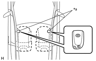
*a
Inspection Point
Check the No. 2 indoor electrical key antenna assembly (center pillar RH) and No. 2 indoor electrical key antenna assembly (center pillar LH).
When the electrical key transmitter sub-assembly is at either inspection point, check that the wireless door lock buzzer sounds.
Body Electrical > Entry&Start > Utility
Tester Display
Communication Check(Key Diag Mode)
-
*a
Inspection Point
Check the No. 1 indoor electrical key antenna assembly (front floor).
When the electrical key transmitter sub-assembly is at either inspection point, check that the wireless door lock buzzer sounds.
Body Electrical > Entry&Start > Utility
Tester Display
Communication Check(Key Diag Mode)
-
*a
Inspection Point
Check the No. 1 indoor electrical key antenna assembly (rear floor) (for 3 Door).
When the electrical key transmitter sub-assembly is at either inspection point, check that the wireless door lock buzzer sounds.
Body Electrical > Entry&Start > Utility
Tester Display
Communication Check(Key Diag Mode)
Tip:If the buzzer sounds, it can be determined that the vehicle interior transmitters are operating normally.
It is possible to check which indoor electrical key antenna assembly (center pillar RH, center pillar LH, front floor or rear floor) is operating by the sounding of the buzzer.
If the buzzer does not sound for any indoor electrical key antenna assembly, the certification ECU (smart key ECU assembly) circuit may be malfunctioning.
OK
Wireless door lock buzzer sounds.
Result
Result
Proceed to
Center pillar RH/LH operation check fails
A
Front floor operation check fails
B
Rear floor operation check fails
C
All operation checks fail
D
All operation checks normal
E
B CHECK HARNESS AND CONNECTOR (CERTIFICATION ECU (SMART KEY ECU ASSEMBLY) - NO. 1 INDOOR ELECTRICAL KEY ANTENNA ASSEMBLY (FRONT FLOOR))Click here
C CHECK HARNESS AND CONNECTOR (CERTIFICATION ECU (SMART KEY ECU ASSEMBLY) - NO. 1 INDOOR ELECTRICAL KEY ANTENNA ASSEMBLY (REAR FLOOR))Click here
D REPLACE CERTIFICATION ECU (SMART KEY ECU ASSEMBLY)
E CHECK ENTRY AND START SYSTEM (VEHICLE INTERIOR DETECTION)Click here
CHECK ENTRY DOOR LOCK OPERATION
Check the operation of the entry lock and unlock functions of the driver side door.
OK
Entry lock and unlock functions operate normally.
Result
Result
Proceed to
OK (for LHD)
A
NG (for LHD)
B
OK (for RHD)
C
NG (for RHD)
D
B CHECK HARNESS AND CONNECTOR (CERTIFICATION ECU (SMART KEY ECU ASSEMBLY - NO. 2 INDOOR ELECTRICAL KEY ANTENNA ASSEMBLY (CENTER PILLAR LH))Click here
C CHECK HARNESS AND CONNECTOR (CERTIFICATION ECU (SMART KEY ECU ASSEMBLY - NO. 2 INDOOR ELECTRICAL KEY ANTENNA ASSEMBLY (CENTER PILLAR LH))Click here
D CHECK HARNESS AND CONNECTOR (CERTIFICATION ECU (SMART KEY ECU ASSEMBLY - NO. 2 INDOOR ELECTRICAL KEY ANTENNA ASSEMBLY (CENTER PILLAR RH))Click here
CHECK HARNESS AND CONNECTOR (CERTIFICATION ECU (SMART KEY ECU ASSEMBLY - NO. 2 INDOOR ELECTRICAL KEY ANTENNA ASSEMBLY (CENTER PILLAR RH))
Disconnect the E50 certification ECU (smart key ECU assembly) connector.
Disconnect the K19 No. 2 indoor electrical key antenna assembly (center pillar RH) connector.
Measure the resistance according to the value(s) in the table below.
Standard Resistance
Tester Connection
Condition
Specified Condition
E50-6 (CLG2) - K19-1 (ANTE2)
Always
Below 1 Ω
E50-23 (CG2B) - K19-3 (CLGB)
Always
Below 1 Ω
E50-6 (CLG2) or K19-1 (ANTE2) - Body ground
Always
10 kΩ or higher
E50-23 (CG2B) or K19-3 (CLGB) - Body ground
Always
10 kΩ or higher
Result
Proceed to
OK
NG
NG REPAIR OR REPLACE HARNESS OR CONNECTOR
CHECK ENTRY AND START SYSTEM (VEHICLE INTERIOR DETECTION)
Reconnect the E50 certification ECU (smart key ECU assembly) connector.
Reconnect the K19 No. 2 indoor electrical key antenna assembly (center pillar RH) connector.
Get into the vehicle while carrying the electrical key transmitter sub-assembly.
Move the shift lever to N.*1
Depress the brake pedal*1 or clutch pedal*2.
Check that the smart warning light in the combination meter assembly illuminates (green), and then press the engine switch and check that the engine starts.
*1: for Multi-Mode Manual Transaxle
*2: for Manual Transaxle
Result
Result
Proceed to
Engine does not start
A
Engine starts normally
B
B END (CONNECTOR WAS NOT CONNECTED SECURELY)
CHECK CERTIFICATION ECU (SMART KEY ECU ASSEMBLY) (OUTPUT TO NO. 2 INDOOR ELECTRICAL KEY ANTENNA ASSEMBLY (CENTER PILLAR RH))
Using an oscilloscope, check the waveform.
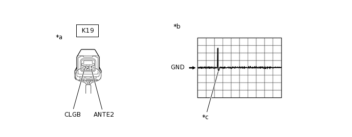
*a
Component with harness connected
(No. 2 Indoor Electrical Key Antenna Assembly (Center Pillar RH))
*b
Waveform 1
*c
Trigger switch ON
-
-
OK
Tester Connection
Condition
Tool Setting
Specified Condition
K19-1 (ANTE2) - K19-3 (CLGB)
Procedure:
Engine switch off
All doors closed
-
No pulse generation
Procedure:
Engine switch off
All doors closed
While carrying the electrical key transmitter sub-assembly, press the trigger switch on the front door outside handle assembly (for front passenger door)
2 V/DIV., 500 ms./DIV.
Pulse generation
(See waveform 1)
Result
Proceed to
OK
NG
NG REPLACE CERTIFICATION ECU (SMART KEY ECU ASSEMBLY)
CHECK HARNESS AND CONNECTOR (CERTIFICATION ECU (SMART KEY ECU ASSEMBLY - NO. 2 INDOOR ELECTRICAL KEY ANTENNA ASSEMBLY (CENTER PILLAR LH))
Disconnect the E50 certification ECU (smart key ECU assembly) connector.
Disconnect the K33 No. 2 indoor electrical key antenna assembly (center pillar LH) connector.
Measure the resistance according to the value(s) in the table below.
Standard Resistance
Tester Connection
Condition
Specified Condition
E50-31 (CLG1) - K33-1 (ANTE1)
Always
Below 1 Ω
E50-30 (CG1B) - K33-3 (CLGB)
Always
Below 1 Ω
E50-31 (CLG1) or K33-1 (ANTE1) - Body ground
Always
10 kΩ or higher
E50-30 (CG1B) or K33-3 (CLGB) - Body ground
Always
10 kΩ or higher
Result
Proceed to
OK
NG
NG REPAIR OR REPLACE HARNESS OR CONNECTOR
CHECK ENTRY AND START SYSTEM (VEHICLE INTERIOR DETECTION)
Reconnect the E50 certification ECU (smart key ECU assembly) connector.
Reconnect the K33 No. 2 indoor electrical key antenna assembly (center pillar LH) connector.
Get into the vehicle while carrying the electrical key transmitter sub-assembly.
Move the shift lever to N.*1
Depress the brake pedal*1 or clutch pedal*2.
Check that the smart warning light in the combination meter assembly illuminates (green), and then press the engine switch and check that the engine starts.
*1: for Multi-Mode Manual Transaxle
*2: for Manual Transaxle
Result
Result
Proceed to
Engine does not start
A
Engine starts normally
B
B END (CONNECTOR WAS NOT CONNECTED SECURELY)
CHECK CERTIFICATION ECU (SMART KEY ECU ASSEMBLY) (OUTPUT TO NO. 2 INDOOR ELECTRICAL KEY ANTENNA ASSEMBLY (CENTER PILLAR LH))
Using an oscilloscope, check the waveform.
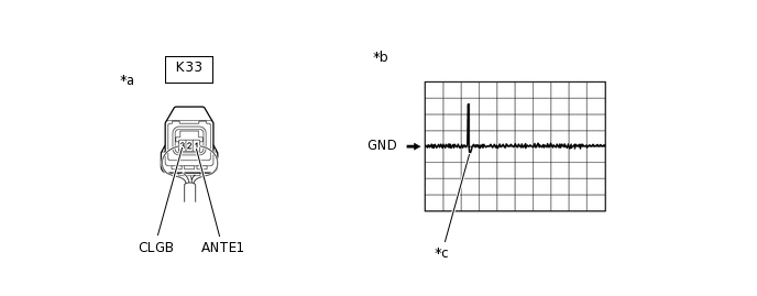
*a
Component with harness connected
(No. 2 Indoor Electrical Key Antenna Assembly (Center Pillar LH))
*b
Waveform 1
*c
Trigger switch ON
-
-
OK
Tester Connection
Condition
Tool Setting
Specified Condition
K33-1 (ANTE1) - K33-3 (CLGB)
Procedure:
Engine switch off
All doors closed
-
No pulse generation
Procedure:
Engine switch off
All doors closed
While carrying the electrical key transmitter sub-assembly, press the trigger switch on the front door outside handle assembly (for driver door)
2 V/DIV., 500 ms./DIV.
Pulse generation
(See waveform 1)
Result
Proceed to
OK
NG
NG REPLACE CERTIFICATION ECU (SMART KEY ECU ASSEMBLY)
CHECK HARNESS AND CONNECTOR (CERTIFICATION ECU (SMART KEY ECU ASSEMBLY - NO. 2 INDOOR ELECTRICAL KEY ANTENNA ASSEMBLY (CENTER PILLAR LH))
Disconnect the E50 certification ECU (smart key ECU assembly) connector.
Disconnect the K19 No. 2 indoor electrical key antenna assembly (center pillar LH) connector.
Measure the resistance according to the value(s) in the table below.
Standard Resistance
Tester Connection
Condition
Specified Condition
E50-6 (CLG2) - K19-1 (ANTE2)
Always
Below 1 Ω
E50-23 (CG2B) - K19-3 (CLGB)
Always
Below 1 Ω
E50-6 (CLG2) or K19-1 (ANTE2) - Body ground
Always
10 kΩ or higher
E50-23 (CG2B) or K19-3 (CLGB) - Body ground
Always
10 kΩ or higher
Result
Proceed to
OK
NG
NG REPAIR OR REPLACE HARNESS OR CONNECTOR
CHECK ENTRY AND START SYSTEM (VEHICLE INTERIOR DETECTION)
Reconnect the E50 certification ECU (smart key ECU assembly) connector.
Reconnect the K19 No. 2 indoor electrical key antenna assembly (center pillar LH) connector.
Get into the vehicle while carrying the electrical key transmitter sub-assembly.
Move the shift lever to N.*1
Depress the brake pedal*1 or clutch pedal*2.
Check that the smart warning light in the combination meter assembly illuminates (green), and then press the engine switch and check that the engine starts.
*1: for Multi-Mode Manual Transaxle
*2: for Manual Transaxle
Result
Result
Proceed to
Engine does not start
A
Engine starts normally
B
B END (CONNECTOR WAS NOT CONNECTED SECURELY)
CHECK CERTIFICATION ECU (SMART KEY ECU ASSEMBLY) (OUTPUT TO NO. 2 INDOOR ELECTRICAL KEY ANTENNA ASSEMBLY (CENTER PILLAR LH))
Using an oscilloscope, check the waveform.
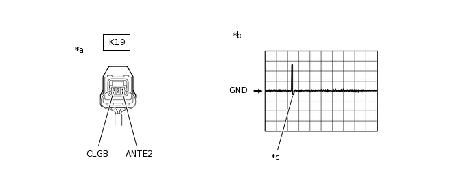
*a
Component with harness connected
(No. 2 Indoor Electrical Key Antenna Assembly (Center Pillar LH))
*b
Waveform 1
*c
Trigger switch ON
-
-
OK
Tester Connection
Condition
Tool Setting
Specified Condition
K19-1 (ANTE2) - K19-3 (CLGB)
Procedure:
Engine switch off
All doors closed
-
No pulse generation
Procedure:
Engine switch off
All doors closed
While carrying the electrical key transmitter sub-assembly, press the trigger switch on the front door outside handle assembly (for front passenger door)
2 V/DIV., 500 ms./DIV.
Pulse generation
(See waveform 1)
Result
Proceed to
OK
NG
NG REPLACE CERTIFICATION ECU (SMART KEY ECU ASSEMBLY)
CHECK HARNESS AND CONNECTOR (CERTIFICATION ECU (SMART KEY ECU ASSEMBLY - NO. 2 INDOOR ELECTRICAL KEY ANTENNA ASSEMBLY (CENTER PILLAR RH))
Disconnect the E50 certification ECU (smart key ECU assembly) connector.
Disconnect the K33 No. 2 indoor electrical key antenna assembly (center pillar RH) connector.
Measure the resistance according to the value(s) in the table below.
Standard Resistance
Tester Connection
Condition
Specified Condition
E50-31 (CLG1) - K33-1 (ANTE1)
Always
Below 1 Ω
E50-30 (CG1B) - K33-3 (CLGB)
Always
Below 1 Ω
E50-31 (CLG1) or K33-1 (ANTE1) - Body ground
Always
10 kΩ or higher
E50-30 (CG1B) or K33-3 (CLGB) - Body ground
Always
10 kΩ or higher
Result
Proceed to
OK
NG
NG REPAIR OR REPLACE HARNESS OR CONNECTOR
CHECK ENTRY AND START SYSTEM (VEHICLE INTERIOR DETECTION)
Reconnect the E50 certification ECU (smart key ECU assembly) connector.
Reconnect the K33 No. 2 indoor electrical key antenna assembly (center pillar RH) connector.
Get into the vehicle while carrying the electrical key transmitter sub-assembly.
Move the shift lever to N.*1
Depress the brake pedal*1 or clutch pedal*2.
Check that the smart warning light in the combination meter assembly illuminates (green), and then press the engine switch and check that the engine starts.
*1: for Multi-Mode Manual Transaxle
*2: for Manual Transaxle
Result
Result
Proceed to
Engine does not start
A
Engine starts normally
B
B END (CONNECTOR WAS NOT CONNECTED SECURELY)
CHECK CERTIFICATION ECU (SMART KEY ECU ASSEMBLY) (OUTPUT TO NO. 2 INDOOR ELECTRICAL KEY ANTENNA ASSEMBLY (CENTER PILLAR RH))
Using an oscilloscope, check the waveform.

*a
Component with harness connected
(No. 2 Indoor Electrical Key Antenna Assembly (Center Pillar RH))
*b
Waveform 1
*c
Trigger switch ON
-
-
OK
Tester Connection
Condition
Tool Setting
Specified Condition
K33-1 (ANTE1) - K33-3 (CLGB)
Procedure:
Engine switch off
All doors closed
-
No pulse generation
Procedure:
Engine switch off
All doors closed
While carrying the electrical key transmitter sub-assembly, press the trigger switch on the front door outside handle assembly (for driver door)
2 V/DIV., 500 ms./DIV.
Pulse generation
(See waveform 1)
Result
Proceed to
OK
NG
NG REPLACE CERTIFICATION ECU (SMART KEY ECU ASSEMBLY)
CHECK HARNESS AND CONNECTOR (CERTIFICATION ECU (SMART KEY ECU ASSEMBLY) - NO. 1 INDOOR ELECTRICAL KEY ANTENNA ASSEMBLY (FRONT FLOOR))
Disconnect the E50 certification ECU (smart key ECU assembly) connector.
Disconnect the E52 No. 1 indoor electrical key antenna assembly (front floor) connector.
Measure the resistance according to the value(s) in the table below.
Standard Resistance
Tester Connection
Condition
Specified Condition
E50-9 (CLG5) - E52-1 (ANTE5)
Always
Below 1 Ω
E50-25 (CG5B) - E52-3 (CLGB)
Always
Below 1 Ω
E50-9 (CLG5) or E52-1 (ANTE5) - Body ground
Always
10 kΩ or higher
E50-25 (CG5B) or E52-3 (CLGB) - Body ground
Always
10 kΩ or higher
Result
Proceed to
OK
NG
NG REPAIR OR REPLACE HARNESS OR CONNECTOR
CHECK ENTRY AND START SYSTEM (VEHICLE INTERIOR DETECTION)
Reconnect the E50 certification ECU (smart key ECU assembly) connector.
Reconnect the E52 No. 1 indoor electrical key antenna assembly (front floor) connector.
Get into the vehicle while carrying the electrical key transmitter sub-assembly.
Move the shift lever to N.*1
Depress the brake pedal*1 or clutch pedal*2.
Check that the smart warning light in the combination meter assembly illuminates (green), and then press the engine switch and check that the engine starts.
*1: for Multi-Mode Manual Transaxle
*2: for Manual Transaxle
Result
Result
Proceed to
Engine does not start
A
Engine starts normally
B
B END (CONNECTOR WAS NOT CONNECTED SECURELY)
CHECK CERTIFICATION ECU (SMART KEY ECU ASSEMBLY) (OUTPUT TO NO. 1 INDOOR ELECTRICAL KEY ANTENNA ASSEMBLY (FRONT FLOOR))
Using an oscilloscope, check the waveform.

*a
Component with harness connected
(No. 1 Indoor Electrical Key Antenna Assembly (Front Floor)
*b
Waveform 1
*c
Door open
*d
Within approximately 30 seconds after the door is closed
OK
Tester Connection
Condition
Tool Setting
Specified Condition
E52-1 (ANTE5) - E52-3 (CLGB)
Procedure:
Electrical key transmitter sub-assembly not inside vehicle
Door is open → closed
2 V/DIV., 500 ms./DIV.
Pulse generation
(See waveform 1)
Result
Proceed to
OK
NG
NG REPLACE CERTIFICATION ECU (SMART KEY ECU ASSEMBLY)
CHECK HARNESS AND CONNECTOR (CERTIFICATION ECU (SMART KEY ECU ASSEMBLY) - NO. 1 INDOOR ELECTRICAL KEY ANTENNA ASSEMBLY (REAR FLOOR))
Disconnect the E50 certification ECU (smart key ECU assembly) connector.
Disconnect the K27 No. 1 indoor electrical key antenna assembly (rear floor) connector.
Measure the resistance according to the value(s) in the table below.
Standard Resistance
Tester Connection
Condition
Specified Condition
E50-26 (CLG6) - K27-1 (ANTE6)
Always
Below 1 Ω
E50-27 (CG6B) - K27-3 (CLGB)
Always
Below 1 Ω
E50-26 (CLG6) or K27-1 (ANTE6) - Body ground
Always
10 kΩ or higher
E50-27 (CG6B) or K27-3 (CLGB) - Body ground
Always
10 kΩ or higher
Result
Proceed to
OK
NG
NG REPAIR OR REPLACE HARNESS OR CONNECTOR
CHECK ENTRY AND START SYSTEM (VEHICLE INTERIOR DETECTION)
Reconnect the E50 certification ECU (smart key ECU assembly) connector.
Reconnect the K27 No. 1 indoor electrical key antenna assembly (rear floor) connector.
Get into the vehicle while carrying the electrical key transmitter sub-assembly.
Move the shift lever to N.*1
Depress the brake pedal*1 or clutch pedal*2.
Check that the smart warning light in the combination meter assembly illuminates (green), and then press the engine switch and check that the engine starts.
*1: for Multi-Mode Manual Transaxle
*2: for Manual Transaxle
Result
Result
Proceed to
Engine does not start
A
Engine starts normally
B
B END (CONNECTOR WAS NOT CONNECTED SECURELY)
CHECK CERTIFICATION ECU (SMART KEY ECU ASSEMBLY) (OUTPUT TO NO. 1 INDOOR ELECTRICAL KEY ANTENNA ASSEMBLY (REAR FLOOR))
Using an oscilloscope, check the waveform.
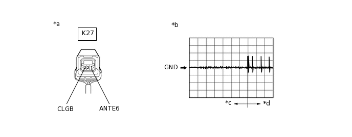
*a
Component with harness connected
(No. 1 Indoor Electrical Key Antenna Assembly (Rear Floor)
*b
Waveform 1
*c
Door open
*d
Within approximately 30 seconds after the door is closed
OK
Tester Connection
Condition
Tool Setting
Specified Condition
K27-1 (ANTE6) - K27-3 (CLGB)
Procedure:
Electrical key transmitter sub-assembly not inside vehicle
Door is open → closed
2 V/DIV., 500 ms./DIV.
Pulse generation
(See waveform 1)
Result
Proceed to
OK
NG
NG REPLACE CERTIFICATION ECU (SMART KEY ECU ASSEMBLY)
CHECK ENTRY AND START SYSTEM (VEHICLE INTERIOR DETECTION)
Get into the vehicle while carrying the electrical key transmitter sub-assembly.
Move the shift lever to N.*1
Depress the brake pedal*1 or clutch pedal*2.
Check that the smart warning light in the combination meter assembly illuminates (green), and then press the engine switch and check that the engine starts.
*1: for Multi-Mode Manual Transaxle
*2: for Manual Transaxle
OK
Engine starts normally.
Result
Proceed to
OK
NG
NG REPLACE CERTIFICATION ECU (SMART KEY ECU ASSEMBLY)