POWER STEERING SYSTEM, Diagnostic DTC:C1528/12
| DTC Code | DTC Name |
|---|---|
| C1528/12 | Motor Rotation Angle Sensor Malfunction |
DESCRIPTION
The motor rotation angle sensor detects the motor rotation angle and sends this information to the power steering ECU assembly.
| DTC No. | DTC Detection Condition | Trouble Area |
|---|---|---|
| C1528/12 | Motor rotation angle sensor malfunction |
|
WIRING DIAGRAM
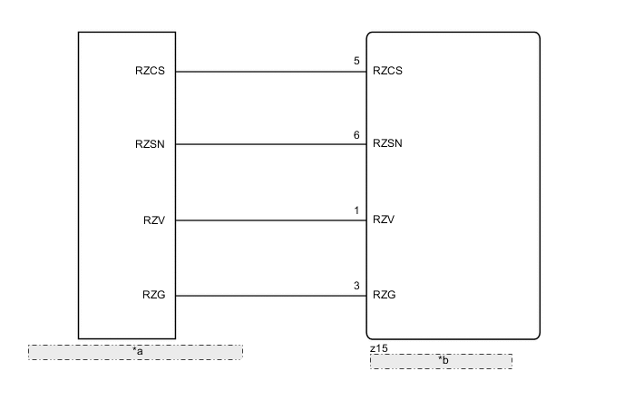
| *a | Motor Rotation Angle Sensor (built into Steering Column Assembly) |
| *b | Power Steering ECU Assembly |
CAUTION / NOTICE / HINT
Note
-
If the power steering ECU assembly has been replaced with a new one, perform assist map writing and rotation angle sensor value initialization torque sensor zero point calibration after performing the initialization of the torque sensor zero point value Click here.
-
If the steering column assembly has been replaced with a new one, perform rotation angle sensor value initialization torque sensor zero point calibration after performing the initialization of the torque sensor zero point value Click here.
PROCEDURE
-
CHECK CONNECTOR CONNECTION CONDITION
-
Check the installation condition of the motor rotation angle sensor connector.
OK Motor rotation angle sensor connector is securely connected to the power steering ECU assembly.
NG 
CONNECT CONNECTOR
OK 
-
-
READ VALUE USING GTS
-
Turn the power switch off.
-
Connect the GTS to the DLC3.
-
Turn the power switch on (READY).
-
Turn the GTS on.
-
Enter the following menus: Chassis / EMPS / Data List.
-
Select the item "Motor Rotation Angle" in the Data List and read the value displayed on the GTS.
EMPS Tester Display Measurement Item/Range Normal Condition Diagnostic Note Motor Rotation Angle Motor rotation angle/
Min.: 0.000 deg
Max.: 1441.770 deg
During steering operation, motor rotation angle value changes from 0 to 360° Power switch on (READY) and steering wheel being turned OK During steering operation, motor rotation angle value changes from 0 to 360°.
OK
REPLACE POWER STEERING ECU ASSEMBLY Click here
NG
-
-
CHECK STEERING COLUMN ASSEMBLY
-
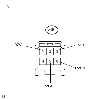
Text in Illustration *a Front view of wire harness connector
(to Motor Rotation Angle Sensor)
Disconnect the connector from the motor rotation angle sensor.
-
Measure the resistance according to the value(s) in the table below.
Standard Resistance Tester Connection Condition Specified Condition z15-6 (RZSN) - z15-3 (RZG) Always 75.2 to 112.8 Ω z15-1 (RZV) - z15-3 (RZG) Always 27.6 to 41.4 Ω z15-5 (RZCS) - z15-3 (RZG) Always 73.2 to 110.8 Ω
OK
REPLACE POWER STEERING ECU ASSEMBLY Click here
NG
REPLACE STEERING COLUMN ASSEMBLY Click here
-