LEXUS PARKING ASSIST-SENSOR SYSTEM(w/o Intelligent Clearance Sonar System) OPERATION CHECK
-
INITIAL CHECK
-
Engine switch on (IG) (LEXUS parking assist-sensor system off).
-
LEXUS parking assist-sensor system on and check an indication state of the vehicle mark.
Tech Tips
-
During the initial check, only malfunction detection is performed. Obstacle detection is not performed.
-
A frozen indication is displayed if the ultrasonic sensor is frozen.
-
If an open circuit occurs in an ultrasonic sensor circuit or a malfunction is detected in a sensor (ultrasonic sensor), an open circuit indication is displayed.
-
-
-
MALFUNCTION DISPLAY (MULTI-INFORMATION DISPLAY)
-
Open circuit indication
-
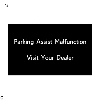
*a Open circuit indication If there is an open circuit between the ultrasonic sensor and the clearance warning ECU assembly or a sensor is malfunctioning, the malfunction is displayed as shown in the illustration.
-
-
Frozen indication
-
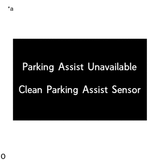
*a Frozen indication If a sensor is covered with foreign matter, such as mud or snow, the affected sensor is displayed as shown in the illustration.
Tech Tips
If a frozen indication is displayed, proceed to "Sensor Frozen Indication (Dirty or Frozen)".
-
-
Communication malfunction indication
-
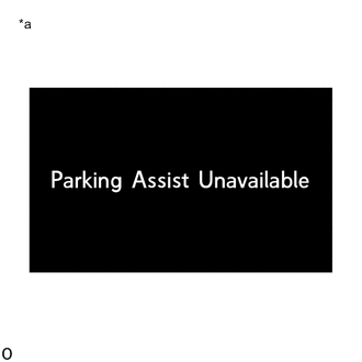
*a Communication malfunction indication When a CAN communication malfunction occurs between the ECM, combination meter assembly, and clearance warning ECU assembly, they are displayed in the same way as shown in the illustration
-
-
-
DETECTION RANGE MEASUREMENT AND DISPLAY INSPECTION
Note
The following measurement and inspection will be performed with the shift lever in a position other than P. Be sure to apply the parking lever and depress the brake pedal firmly to prevent the vehicle from moving.
-
Turn the engine switch on (IG).
-
Turn the LEXUS parking assist-sensor system on.
-
Detection range measurement:
-
Move the shift lever according to the table below.
Measurement Area Shift Lever Position Front Corner Sensor (front corner ultrasonic sensor) In any position other than P Front Center Sensor (front center ultrasonic sensor) In any position other than P or R Rear Corner Sensor (rear corner ultrasonic sensor) R Rear Center Sensor (rear center ultrasonic sensor) -
Move a 60 mm (2.4 in.) diameter pole near each sensor to measure its detection range. When measuring the Longest-range detection of the front center sensor and the rear center sensor, use a wall or equivalent.
Note
These detection ranges are applicable when positioning the 60 mm (2.4 in.) diameter pole parallel or perpendicular to the ground. The detection range varies depending on the measuring method and type of obstacle (such as walls).
Tech Tips
Have an assistant move the pole.
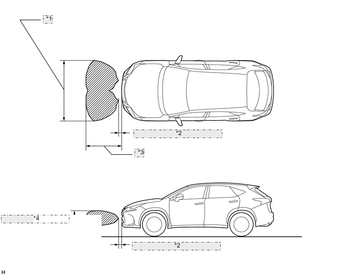
Figure 1. Front Corner Sensor and Rear Corner Sensor Detection Range
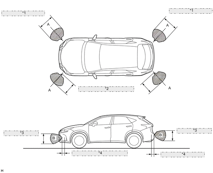
*1 Approximately 850 mm (33.5 in.) *2 Approximately 600 mm (23.6 in.) *3 Approximately 450 mm (17.7 in.) *4 Approximately 200 mm (7.87 in.) Note
The front corner sensor and rear corner sensor side view detection range (hatched area labeled (B)) represents the cross section of the top view detection range (A). The hatched area (B) does not represent the entire side view detection range.
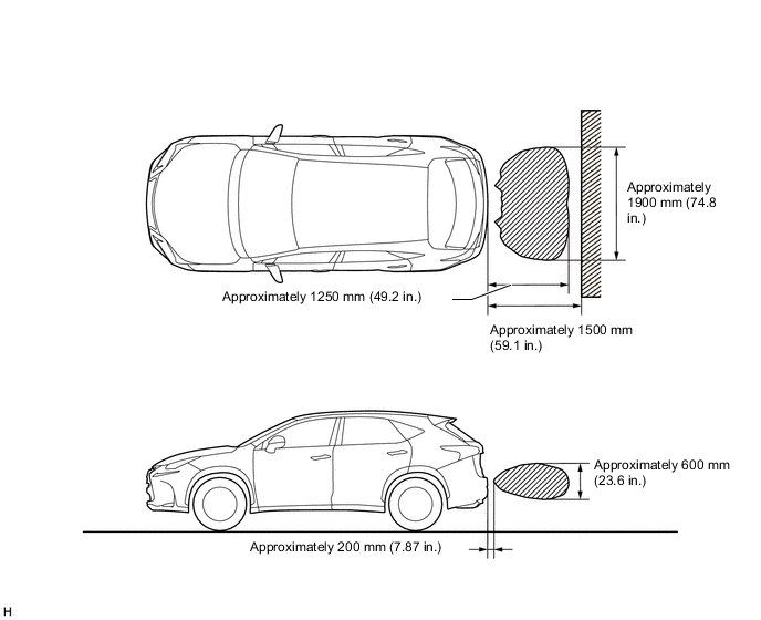
Figure 2. Front Center Sensor Detection Range
*1 Approximately 2000 mm (78.7 in.) *2 Approximately 200 mm (7.87 in.) *3 Approximately 1000 mm (39.4 in.) *4 Approximately 500 mm (19.7 in.) Figure 3. Rear Center Sensor Detection Range
-
-
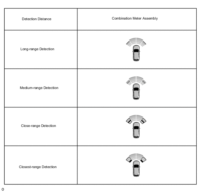
Front corner sensor display and buzzer operation check
-
When the front corner ultrasonic sensor (front corner sensor) have detected an obstacle, check the displays and check that the buzzer sounds.
Operation Condition Engine switch LEXUS Parking Assist-sensor System Shift Lever Position Vehicle Speed* On (IG) On In any position other than P
-
Less than approximately 15 km/h (9 mph) if speed is increasing
-
Less than approximately 10 km/h (6 mph) if speed is decreasing
*: When the shift position is R, the system operates at any vehicle speed.
Figure 4. Multi-display Assembly Icon
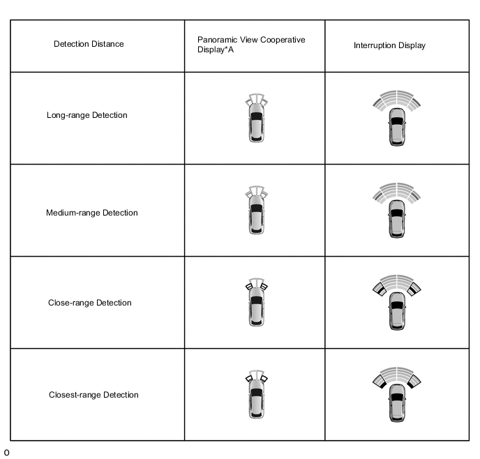
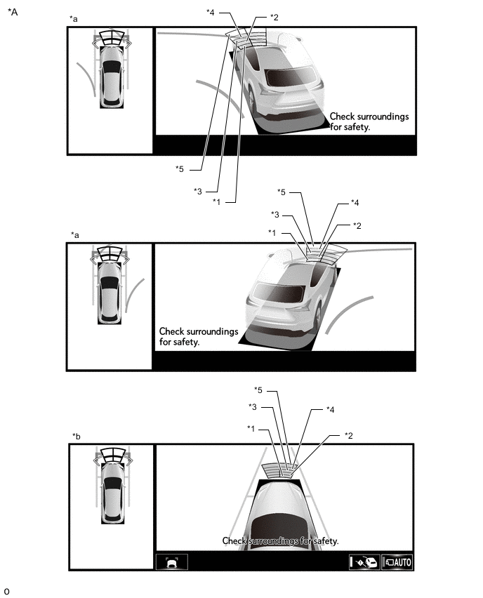
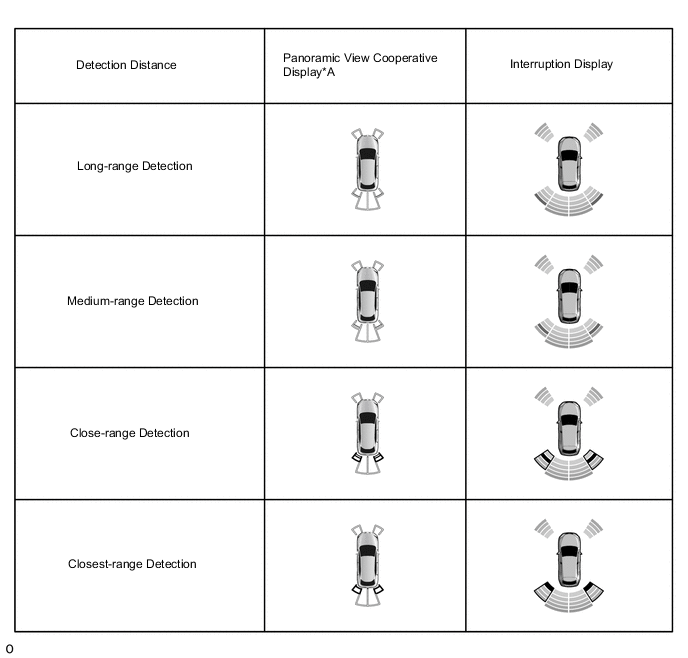
*A w/ Panoramic View Monitor System - - Figure 5. Cornering View and Side Clearance View Icon (w/ Panoramic View Monitor System)
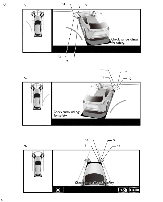
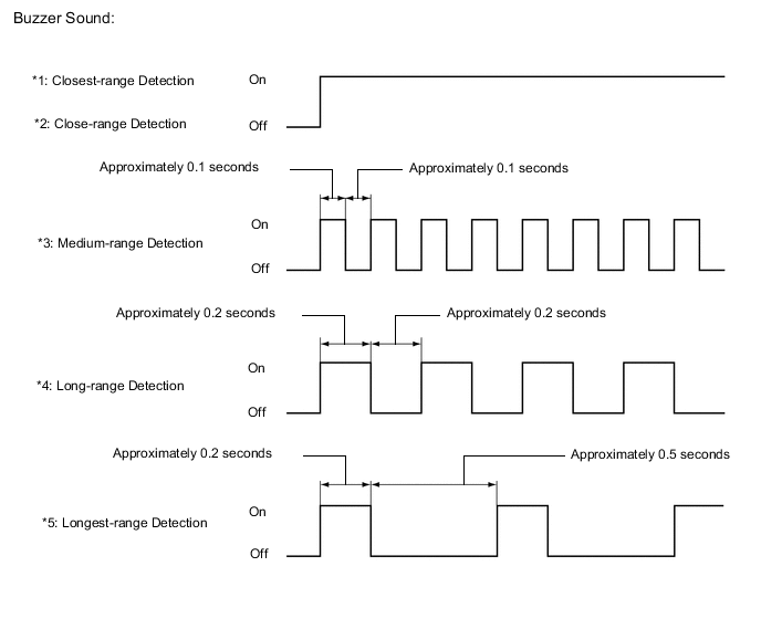
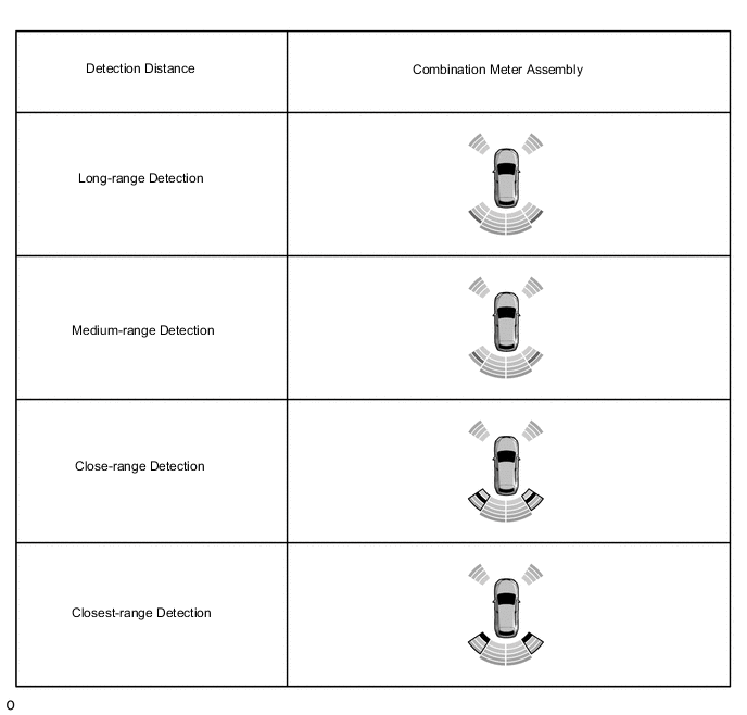
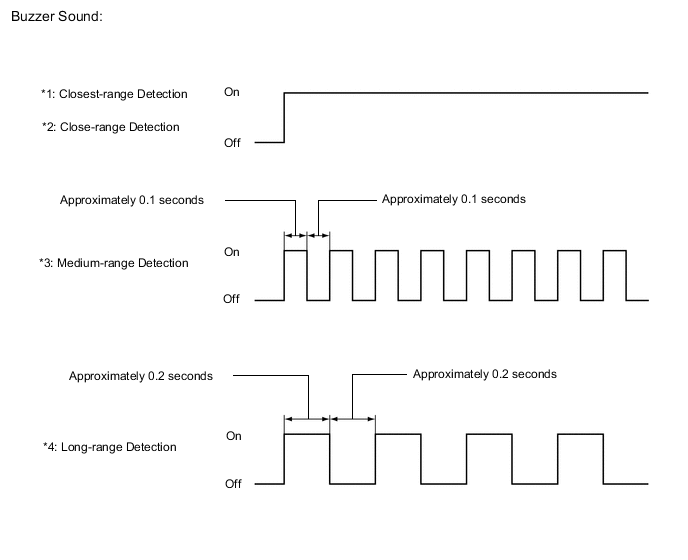
*A Example - - *a Panoramic View and Cornering View Display *b Panoramic View and Side Clearance View Display *1 Closest-range *2 Close-range *3 Medium-range *4 Long-range Figure 6. Combination Meter Assembly Icon

Tech Tips
Ultrasonic waves are used to measure the detection range; however, the detection range may vary depending on the ambient temperature.
-
-
-
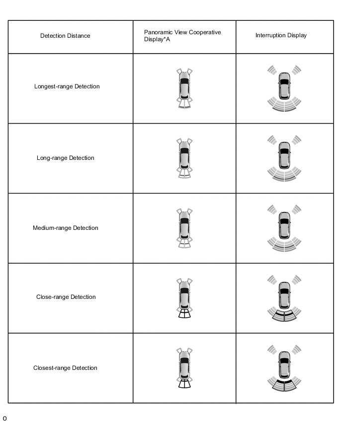
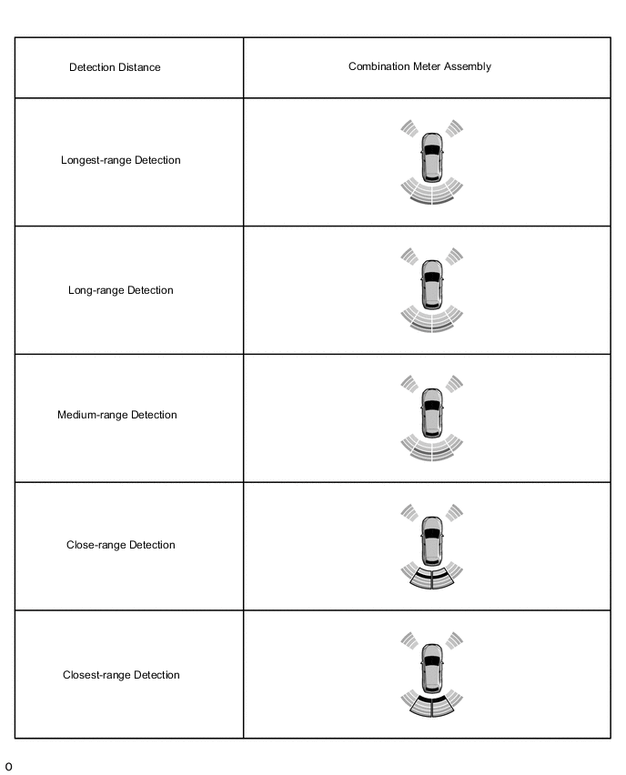
Front center sensor display and buzzer operation check
-
When the front center ultrasonic sensors (front center sensor) has detected an obstacle, check the display and check that the buzzer sounds.
Operation Condition Engine switch LEXUS Parking Assist-sensor System Shift Lever Position Vehicle Speed On (IG) On In any position other than P or R
-
Less than approximately 15 km/h (9 mph) if speed is increasing
-
Less than approximately 10 km/h (6 mph) if speed is decreasing
Figure 7. Multi-display Assembly Icon
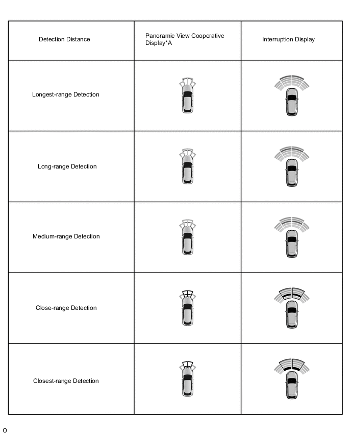
*A w/ Panoramic View Monitor System - - Figure 8. Cornering View and Side Clearance View Icon (w/ Panoramic View Monitor System)
*A Example - - *a Panoramic View and Cornering View Display *b Panoramic View and Side Clearance View Display *1 Closest-range *2 Close-range *3 Medium-range *4 Long-range *5 Longest-range - - Figure 9. Combination Meter Assembly Icon
Tech Tips
Ultrasonic waves are used to measure the detection range; however, the detection range may vary depending on the ambient temperature.
-
-
-
Rear corner sensor display and buzzer operation check
-
When the rear corner ultrasonic sensor (rear corner sensor) has detected an obstacle, check the display and check that the buzzer sounds.
Operation Condition Engine switch LEXUS Parking Assist-sensor System Shift Lever Position Vehicle Speed On (IG) On R - Figure 10. Multi-display Assembly Icon
*A w/ Panoramic View Monitor System - - Figure 11. Combination Meter Assembly Icon
Tech Tips
Ultrasonic waves are used to measure the detection range; however, the detection range may vary depending on the ambient temperature.
-
-
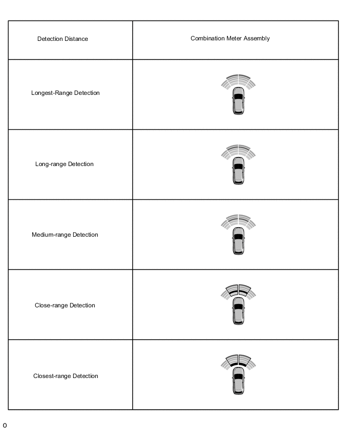
Rear center sensor display and buzzer operation check
-
When the rear center ultrasonic sensors (rear center sensor) have detected an obstacle, check the display and check that the buzzer sounds.
Operation Condition Engine switch LEXUS Parking Assist-sensor System Shift Lever Position Vehicle Speed On (IG) On R - Figure 12. Multi-display Assembly Icon
*A w/ Panoramic View Monitor System - - Figure 13. Combination Meter Assembly Icon

Tech Tips
Ultrasonic waves are used to measure the detection range; however, the detection range may vary depending on the ambient temperature.
-
-