LUBRICATION SYSTEM SYSTEM DIAGRAM
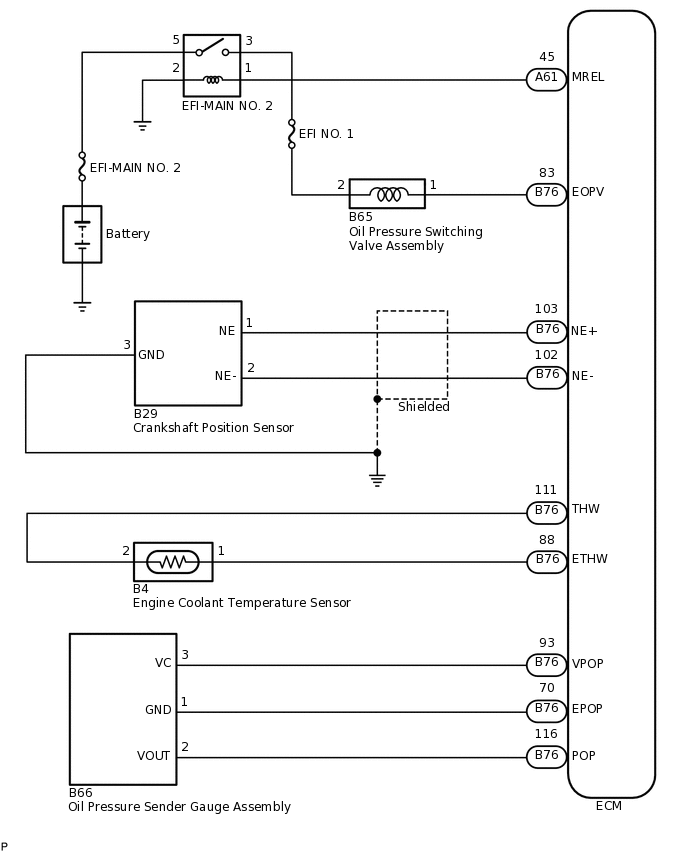
ELECTRICAL CONTROL DIAGRAM
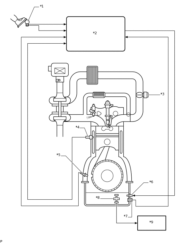
*1
Accelerator Pedal Sensor
*2
ECM
*3
Diesel Throttle Body Assembly
*4
Engine Coolant Temperature Sensor
*5
Crankshaft Position Sensor
*6
Oil Pressure Switching Valve Assembly
*7
Oil Pressure Sender Gauge Assembly
*8
Engine Oil Level Sensor
*9
Combination Meter
-
-
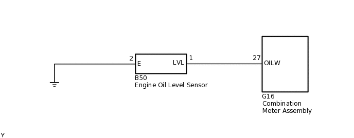
LUBRICATION SYSTEM WIRING DIAGRAM