AIR SUSPENSION SYSTEM, Diagnostic DTC:C1715/15,C1716/16,C1717/17,C1796/96,C1797/97 and C1798/98
| DTC Code | DTC Name |
|---|---|
| C1715/15 | Front Acceleration Sensor RH Malfunction |
| C1716/16 | Front Acceleration Sensor LH Malfunction |
| C1717/17 | Rear Acceleration Sensor Malfunction |
| C1796/96 | (Up & Down) G Sensor FR |
| C1797/97 | (Up & Down) G Sensor FL |
| C1798/98 | (Up & Down) G Sensor Rear |
DESCRIPTION
The acceleration sensor (up and down G sensor) detects the upward and downward acceleration of the vehicle, and outputs it as a voltage to the suspension control ECU. Up and down G sensors are installed in 3 locations: 1) the suspension control ECU, 2) the RH side instrument panel, and 3) behind the deck trim side panel assembly LH. Each up and down G sensor independently detects the upward and downward acceleration. During a test mode inspection, the suspension control ECU reads the fluctuations in each sensor signal. If a sensor signal does not fluctuate, test mode DTCs C1796/96, C1797/97 and C1798/98 are stored.
DTC No. |
Detection Item |
DTC Detection Condition |
Trouble Area |
Warning Indicate |
|---|---|---|---|---|
C1715/15 |
Front Acceleration Sensor RH Malfunction |
Either condition is met:
|
|
Not indicated |
C1716/16 |
Front Acceleration Sensor LH Malfunction |
Either condition is met:
|
Suspension control ECU (front acceleration sensor LH) |
Not indicated |
C1717/17 |
Rear Acceleration Sensor Malfunction |
Either condition is met:
|
|
Not indicated |
C1796/96 |
(Up & Down) G Sensor FR |
On a level surface, the G sensor input is +/- 1.96 m/s2 or more for 1 second or more. |
|
- |
C1797/97 |
(Up & Down) G Sensor FL |
On a level surface, the G sensor input is +/- 1.96 m/s2 or more for 1 second or more. |
Suspension control ECU (front acceleration sensor LH) |
- |
C1798/98 |
(Up & Down) G Sensor Rear |
On a level surface, the G sensor input is +/- 1.96 m/s2 or more for 1 second or more. |
|
- |
If DTCs C1716/16 and C1797/97 are output, replace the suspension control ECU (houses the front acceleration sensor LH).
WIRING DIAGRAM
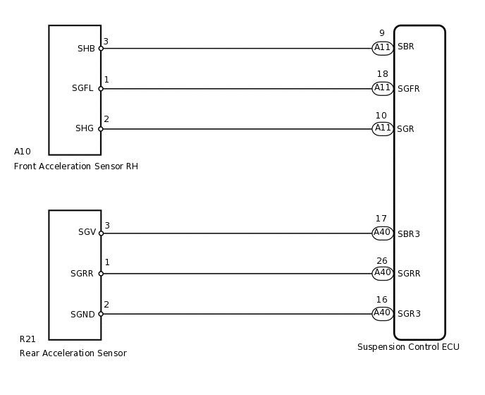
CAUTION / NOTICE / HINT
When replacing the suspension control ECU, perform registration (Click here).
PROCEDURE
READ VALUE USING INTELLIGENT TESTER (G SENSOR)
Turn the engine switch off.
Connect the intelligent tester to the DLC3.
Turn the engine switch on (IG).
Turn the intelligent tester on.
Enter the following menus: Chassis / Air suspension / Data List.
Chassis > Air suspension > Data List
Tester Display
Measurement Item
Range
Normal Condition
Diagnostic Note
(Up&Down)G Sensor FR
Front acceleration sensor RH (up and down)
Min.: -1045.29 m/s2
Max.: 1045.26 m/s2
0 +/- 0.98 m/s2 when stationary
The value changes when the vehicle (Front RH) is bounced.
(Up&Down)G Sensor FL
Front acceleration sensor LH (up and down)
Min.: -1045.29 m/s2
Max.: 1045.26 m/s2
0 +/- 0.98 m/s2 when stationary
The value changes when the vehicle (Front LH) is bounced.
(Up&Down)G Sensor Rear
Rear acceleration sensor (up and down)
Min.: -1045.29 m/s2
Max.: 1045.26 m/s2
0 +/- 0.98 m/s2 when stationary
The value changes when the vehicle (rear) is bounced.
OK
Acceleration value changes.
Result
Result
OK
NG
INSPECT ACCELERATION SENSOR (FRONT RH OR REAR)
-
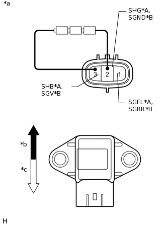
*A
for Front RH
*B
for Rear
*a
Component without harness connected
(Acceleration Sensor)
*b
Up
*c
Down
Check the front acceleration sensor RH (when DTC C1715/15 or C1796/96 is output).
Remove the front acceleration sensor RH.
Connect 3 dry cell batteries of 1.5 V in series.
Connect the positive (+) end of the batteries to terminal 3 (SHB) of the acceleration sensor and the negative (-) end of the batteries to terminal 2 (SHG). Then measure the voltage between terminal 1 (SGFL) and terminal 2 (SHG).
Measure the voltage according to the value(s) in the table below.
Standard Voltage
Tester Connection
Condition
Specified Condition
1 (SGFL) - 2 (SHG)
Sensor in vertical position
Approx. 2.0 to 2.5 V
Sensor tilted left or right from vertical position
Changes between approx. 0.9 and 2.3 V
Check the rear acceleration sensor: (when DTC C1717/17 or C1798/98 is output).
Remove the rear acceleration sensor.
Connect 3 dry cell batteries of 1.5 V in series.
Connect the positive (+) end of the batteries to terminal 3 (SGV) of the acceleration sensor and the negative (-) end of the batteries to terminal 2 (SGND). Then measure the voltage between terminal 1 (SGRR) and terminal 2 (SGND).
Measure the voltage according to the value(s) in the table below.
Standard Voltage
Tester Connection
Condition
Specified Condition
1 (SGRR) - 2 (SGND)
Sensor in vertical position
Approx. 2.0 to 2.5 V
Sensor tilted left or right from vertical position
Changes between approx. 0.9 and 2.3 V
Note:Do not apply a voltage of higher than 6 V.
Tip:When the acceleration sensor is tilted, it may output a different value.
Result
Result
Proceed to
OK
A
NG (Front acceleration sensor RH)
B
NG (Rear acceleration sensor)
C
-
CHECK HARNESS AND CONNECTOR (ACCELERATION SENSOR - SUSPENSION CONTROL ECU)
Check the front acceleration sensor RH (when DTC C1715/15 or C1796/96 is output).
Disconnect the A10 front acceleration sensor RH connector.
Disconnect the A11 suspension control ECU connector.
Measure the resistance according to the value(s) in the table below.
Standard Resistance
Tester Connection
Condition
Specified Condition
A10-1 (SGFL) - A11-18 (SGFR)
Always
Below 1 Ω
A10-2 (SHG) - A11-10 (SGR)
Always
Below 1 Ω
A10-3 (SHB) - A11-9 (SBR)
Always
Below 1 Ω
A10-1 (SGFL) - Body ground
Always
10 kΩ or higher
A10-2 (SHG) - Body ground
Always
10 kΩ or higher
A10-3 (SHB) - Body ground
Always
10 kΩ or higher
Check the rear acceleration sensor: (when DTC C1717/17 or C1798/98 is output).
Disconnect the R21 rear acceleration sensor connector.
Disconnect the A40 suspension control ECU connector.
Measure the resistance according to the value(s) in the table below.
Standard Resistance
Tester Connection
Condition
Specified Condition
R21-1 (SGRR) - A40-26 (SGRR)
Always
Below 1 Ω
R21-2 (SGND) - A40-16 (SGR3)
Always
Below 1 Ω
R21-3 (SGV) - A40-17 (SBR3)
Always
Below 1 Ω
R21-1 (SGRR) - Body ground
Always
10 kΩ or higher
R21-2 (SGND) - Body ground
Always
10 kΩ or higher
R21-3 (SGV) - Body ground
Always
10 kΩ or higher
Result
Result
OK
NG
NG REPAIR OR REPLACE HARNESS OR CONNECTOR