BRAKE BOOSTER(for LHD) INSTALLATION
PROCEDURE
INSTALL BRAKE BOOSTER GASKET
Install a new brake booster gasket to the brake booster assembly.
INSTALL BRAKE BOOSTER ASSEMBLY
Temporarily install the brake booster assembly to the vehicle body.
Note:Do not apply excessive force to the brake lines or refrigerant lines.
Temporarily install the lock nut and brake master cylinder push rod clevis to the brake booster assembly.
Note:Fully tighten the lock nut when adjusting the brake pedal height.
-
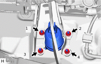
Install the 4 nuts to secure the brake booster assembly.
12.7 N*m
130 kgf*cm
9 ft.*lbf
Note:Tighten the 4 nuts in the order shown in the illustration.
-
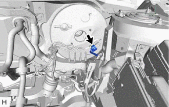
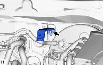
w/ Stop and Start System:
Connect the connector to the vacuum sensor assembly.
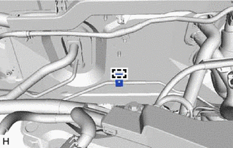
INSTALL FRONT NO. 1 BRAKE TUBE WAY
-
Install the front No. 1 brake tube way to the vehicle body with the bolt.
7.0 N*m
71 kgf*cm
62 in.*lbf
-
INSTALL NO. 3 BRAKE TUBE CLAMP
-
Engage the clamp to install a new No. 3 brake tube clamp.
-
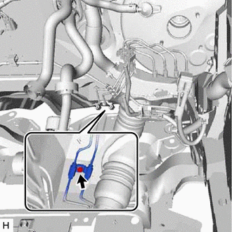
CONNECT CHECK VALVE TO CONNECTOR TUBE HOSE
-
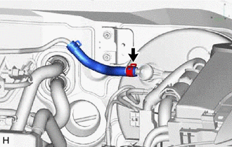
Connect the check valve to connector tube hose to the brake booster assembly and slide the clip to secure it.
-
INSTALL NO. 3 HEATER BRACKET SUB-ASSEMBLY (w/ Combustion Type Power Heater)
Install the No. 3 heater bracket sub-assembly with the nut.
9.8 N*m
100 kgf*cm
87 in.*lbf
INSTALL HEATER PUMP ASSEMBLY (w/ Combustion Type Power Heater)
INSTALL PUSH ROD PIN
INSTALL BRAKE PEDAL RETURN SPRING
CONNECT NO. 2 STEERING INTERMEDIATE SHAFT ASSEMBLY (for 1AD-FTV)
Connect the No. 2 steering intermediate shaft assembly to the steering column assembly.
INSTALL NO. 1 INSTRUMENT PANEL UNDER COVER SUB-ASSEMBLY (w/ Instrument Panel Under Cover)
INSTALL BRAKE ACTUATOR ASSEMBLY
INSTALL BRAKE MASTER CYLINDER SUB-ASSEMBLY
INSPECT AND ADJUST BRAKE PEDAL