FUEL SYSTEM PRECAUTION

CAUTION:
-
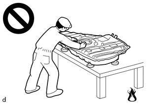
Never perform work on fuel system components near any possible ignition sources.
-
Vaporized fuel could ignite, resulting in a serious accident.
-
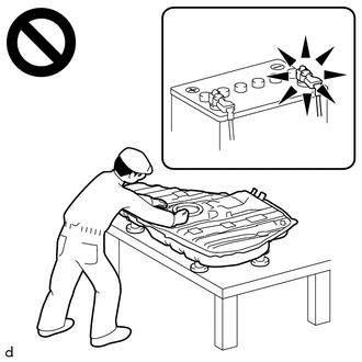
Do not perform work on fuel system components without first disconnecting the cable from the negative (-) battery terminal.
-
Sparks could cause vaporized fuel to ignite, resulting in a serious accident.
-
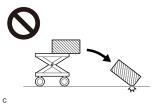
Because the weight of the fuel tank sub-assembly is extremely heavy, make sure to follow the work procedures described in the repair manual.
-
If work is not performed according to the procedures described in the repair manual, there is a danger that the components could fall down.
-
IGNITION SWITCH EXPRESSIONS
Tech Tips
The type of ignition switch used on this model differs depending on specifications of the vehicle.
The expressions listed in the table below are used in this section.
Expression Ignition Switch (Position) Engine Switch (Condition) Ignition switch off LOCK Off (Lock) Ignition switch ACC ACC On (ACC) Ignition switch ON ON On (IG) Engine Start START Start -
PRECAUTION
Note
-
Keep fuel away from rubber or leather parts.
-
After turning the ignition switch off, waiting time may be required before disconnecting the cable from the battery terminal. Therefore, make sure to read the disconnecting the cable from the battery terminal notice before proceeding with work.
-
-
DISCHARGE FUEL SYSTEM PRESSURE
CAUTION:
-
Make sure the engine coolant temperature is 60°C (140°F) or less when performing this procedure.
-
Perform the following procedure to prevent fuel from spraying before removing any fuel system parts.
-
Pressure will still remain in the fuel lines even after performing the following procedure. When disconnecting a fuel line, cover it with a piece of cloth to prevent fuel from spraying or coming out.
-
When discharging fuel system pressure by disconnecting the C/OPN relay:
-
Remove the No. 1 relay block cover.
-
Remove the C/OPN relay.
-
Start the engine. After the engine has stopped on its own, turn the ignition switch off.
Note
Do not increase the engine speed or drive the vehicle while waiting for the engine to stop on its own.
-
Crank the engine again and make sure that the engine does not start.
Tech Tips
DTC P0171 (System Too Lean), P1603 (Engine Stall History), P1604 (Startability Malfunction) and P1605 (Rough Idling) may be stored. Clear the DTCs before proceeding to the next step.
-
Remove the fuel tank cap assembly and discharge the pressure from the fuel tank assembly.
-
Disconnect the cable from the negative (-) battery terminal.
Note
When disconnecting the cable, some systems need to be initialized after the cable is reconnected.
-
Install the C/OPN relay.
-
Install the No. 1 relay block cover.
-
-
When discharging fuel system pressure by disconnecting the fuel pump connector:
-
Disconnect the rear center seat outer belt assembly.
-
Remove the bench type rear seat cushion assembly.
-
Remove the rear seat cushion lock hook.
-
Remove the rear floor service hole cover.
-
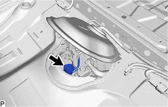
Disconnect the fuel suction tube with pump and gauge assembly connector.
-
Start the engine. After the engine has stopped on its own, turn the ignition switch off.
Note
Do not increase the engine speed or drive the vehicle while waiting for the engine to stop on its own.
-
Crank the engine again and make sure that the engine does not start.
Tech Tips
DTC P0171 (System Too Lean), P1603 (Engine Stall History), P1604 (Startability Malfunction) and P1605 (Rough Idling) may be stored. Clear the DTCs before proceeding to the next step.
-
Remove the fuel tank cap assembly and discharge the pressure from the fuel tank sub-assembly.
-
Disconnect the cable from the negative (-) battery terminal.
Note
When disconnecting the cable, some systems need to be initialized after the cable is reconnected.
-
Connect the fuel suction tube with pump and gauge assembly connector.
-
Install the rear floor service hole cover.
-
Install the rear seat cushion lock hook.
-
Install the bench type rear seat cushion assembly.
-
Connect the rear center seat outer belt assembly.
-
-
-
FUEL LINE
-
When disconnecting a high-pressure fuel line, a large amount of fuel will spray. Perform the following procedure:
-
Discharge fuel system pressure.
-
Disconnect the fuel tube.
-
Drain the fuel remaining inside the fuel tube into a container.
-
Cover the disconnected fuel pipe and fuel tube connector with plastic bags to prevent damage and contamination.
-
-
Metallic Type:
Perform the following procedure when disconnecting a fuel tube connector.
Note
Remove any dirt or foreign matter on the fuel tube connector and fuel pipe before performing this work.
-
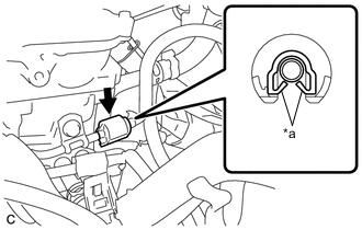
*a Claw Disengage the 2 claws to remove the No. 2 fuel pipe clamp.
Note
Do not reuse the No. 2 fuel pipe clamp.
-
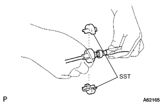
Install SST (fuel hose puller) to the fuel tube connector as shown in the illustration.
- SST
- 09268-21011
-
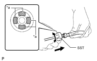
*a Retainer (4 places) Turn SST (fuel hose puller), align the retainers inside the fuel tube connector with the SST (fuel hose puller) chamfers and insert SST (fuel hose puller) into the fuel tube connector.
-
Mount the retainer of the fuel tube connector onto the chamfered part of SST (fuel hose puller).
-
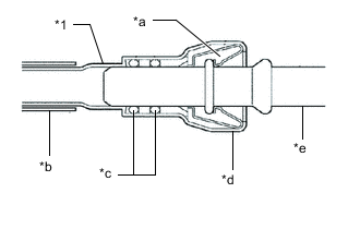
*1 Fuel Tube Sub-assembly *a Retainer *b Nylon Tube *c O-ring *d Fuel Tube Connector *e Fuel Pipe Slide SST (fuel hose puller) and the fuel tube connector together until they make a "click" sound, and then disconnect the fuel tube connector.
Note
-
Do not allow any scratches or foreign matter to get on the parts when disconnecting them as the fuel tube connector has O-rings that seal the fuel pipe.
-
Do not forcibly bend, twist or turn the nylon tube.
-
-
Check if there is any foreign matter on the sealing surfaces of the disconnected fuel lines. Clean them if necessary.
-
Cover the disconnected fuel pipe and fuel tube connector with plastic bags to prevent damage and contamination.
-
-
Metallic Type:
Perform the following procedure when connecting a fuel tube connector.
Note
Check if there is any damage or foreign matter on the connecting parts of the fuel lines.
-
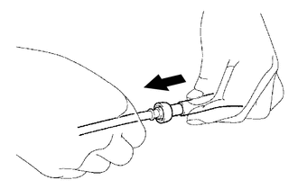

Push Align the fuel tube connector with the fuel pipe, and push the fuel pipe into the fuel tube connector until the fuel tube connector makes a "click" sound. If it is difficult to push the fuel pipe into the fuel tube connector, apply a small amount of clean engine oil to the tip of the fuel pipe.
-
After connecting the fuel lines, check that the fuel pipe and fuel tube connector are securely connected by pulling on them.
-
Engage the 2 claws to install a new No. 2 fuel pipe clamp.
-
Inspect for fuel leaks.
-
-
Quick Type A:
Perform the following procedure when disconnecting a fuel tube connector.
Note
Remove any dirt or foreign matter on the fuel tube connector and fuel pipe before performing this work.
-
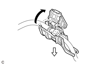
Disengage the claw and remove the No. 1 fuel pipe clamp.
-
Check that there is no dirt or other foreign matter around the fuel tube connector before disconnecting it. Clean the joint if necessary.
-
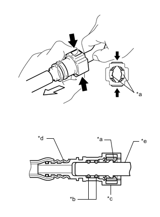
*a Retainer *b O-ring *c Fuel Tube Connector *d Nylon Tube *e Fuel Pipe Pinch 
Pull Pinch the retainer of the fuel tube connector, and then pull the fuel tube connector off of the fuel pipe.
Note
Be sure to disconnect the fuel tube connector by hand.
-
If the fuel tube connector and fuel pipe are stuck, push and pull the fuel tube connector to release it. Pull the fuel tube connector off of the fuel pipe carefully.
Note
-
Be sure to disconnect the fuel tube connector by hand.
-
Do not allow any scratches or foreign matter to get on the parts when disconnecting them as the fuel tube connector has O-rings that seal the fuel pipe.
-
Do not forcibly bend, twist or turn the nylon tube.
-
-
Check if there is any foreign matter on the sealing surfaces of the disconnected fuel lines. Clean them if necessary.
-
Cover the disconnected fuel pipe and fuel tube connector with plastic bags to prevent damage and contamination.
-
-
Quick Type A:
Perform the following procedure when connecting a fuel tube connector.
Note
Check if there is any damage or foreign matter on the connecting parts of the fuel lines.
-
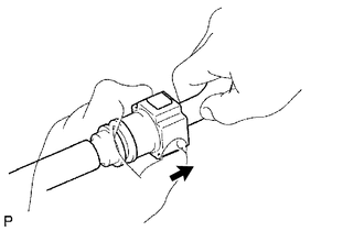
Push Align the fuel tube connector with the fuel pipe, and push them together until the fuel tube connector makes a "click" sound. If it is difficult to push the fuel pipe into the fuel tube connector, apply a small amount of clean engine oil to the tip of the fuel pipe and reinsert it.
-
After connecting the fuel lines, check that the fuel pipe and fuel tube connector are securely connected by pulling on them.
-
Engage the claw and install the No. 1 fuel pipe clamp.
-
Inspect for fuel leaks.
-
-
Quick Type B:
Perform the following procedure when disconnecting a fuel tube connector.
Note
Remove any foreign matter on the fuel tube connector and fuel pipe before performing this work.
-
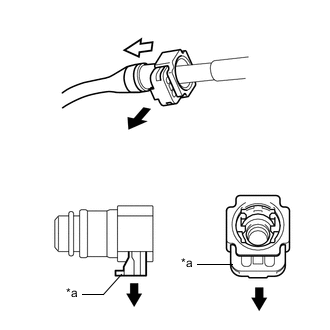
*a Retainer Pull out Pull off Pull out the retainer to disengage the lock claws and pull off the fuel tube connector.
-
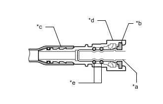
*a Fuel Pipe *b Retainer *c Nylon Tube *d Fuel Tube Connector *e O-ring If the fuel tube connector and fuel pipe are stuck, push and pull the fuel tube connector to release it. Pull the fuel tube connector off of the fuel pipe carefully.
Note
Do not scratch or allow any foreign matter to get on the parts when disconnecting them as the fuel tube connector has O-rings that seal the pipe (fuel pipe).
-
Check that there is no foreign matter on the sealing surfaces of the disconnected fuel lines. Clean them if necessary.
-
Cover the disconnected fuel pipe and fuel tube connector with plastic bags to prevent damage and contamination.
-
-
Quick Type B:
Perform the following procedure when connecting a fuel tube connector.
Note
Check that there is no damage or foreign matter on the connecting parts of the fuel lines.
-
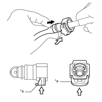
*a Retainer Push Push in Align the fuel tube connector with the fuel pipe and push them together. If it is difficult to push the fuel pipe into the fuel tube connector, apply a small amount of clean gasoline to the tip of the fuel pipe and reinsert it.
-
Connect the fuel lines and push in the retainer. Check that the fuel pipe and fuel tube connector are securely connected by pulling on them.
-
Inspect for fuel leaks.
-
-
Quick Type C:
Perform the following procedure when disconnecting a fuel tube connector.
Note
Remove any foreign matter on the fuel tube connector and fuel pipe before performing this work.
-
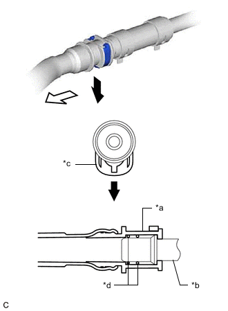
*a Fuel Tube Connector *b Fuel Pipe *c Retainer *d O-ring Pull out Pull off Pull out the retainer to disengage the lock claws and pull off the fuel tube connector.
-
If the fuel tube connector and fuel pipe are stuck, push and pull the fuel tube connector to release it. Pull the fuel tube connector off of the fuel pipe carefully.
Note
Do not scratch or allow any foreign matter to get on the parts when disconnecting them as the fuel tube connector has O-rings that seal the pipe (fuel pipe).
-
Check that there is no foreign matter on the sealing surfaces of the disconnected fuel lines. Clean them if necessary.
-
Cover the disconnected fuel pipe and fuel tube connector with plastic bags to prevent damage and contamination.
-
-
Quick Type C:
Perform the following procedure when connecting a fuel tube connector.
Note
Check that there is no damage or foreign matter on the connecting parts of the fuel lines.
-
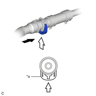
*a Retainer Push Push in Align the fuel tube connector with the fuel pipe and push them together. If it is difficult to push the fuel pipe into the fuel tube connector, apply a small amount of clean gasoline to the tip of the fuel pipe and reinsert it.
-
Connect the fuel lines and push in the retainer. Check that the fuel pipe and fuel tube connector are securely connected by pulling on them.
-
Inspect for fuel leaks.
-
-
Quick Type D:
Perform the following procedure when disconnecting a fuel tube connector.
Note
Remove any dirt or foreign matter on the fuel tube connector and fuel pipe before performing this work.
-
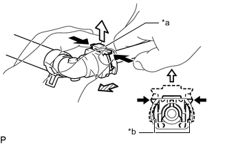
*a Retainer *b Claw Push Pull out 
Pull off Disengage the 2 claws of the retainer. Pull out the retainer and disconnect the fuel tube connector from the fuel pipe.
Note
Be sure to disconnect the fuel tube connector by hand.
-
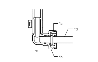
*a Retainer *b Fuel Tube Connector *c O-ring *d Fuel Pipe If the fuel tube connector and fuel pipe are stuck, push and pull the fuel tube connector to release it. Pull the fuel tube connector off of the fuel pipe carefully.
Note
-
Be sure to disconnect the fuel tube connector by hand.
-
Do not allow any scratches or foreign matter to get on the parts when disconnecting them as the fuel tube connector has an O-ring that seals the fuel pipe.
-
-
Check if there is any foreign matter on the sealing surfaces of the disconnected fuel lines. Clean them if necessary.
-
Cover the disconnected fuel pipe and fuel tube connector with plastic bags to prevent damage and contamination.
-
-
Quick Type D:
Perform the following procedure when connecting a fuel tube connector.
Note
Check if there is any damage or foreign matter on the connecting parts of the fuel lines.
-
Align the fuel tube connector with the fuel pipe, and push them together until the fuel tube connector makes a "click" sound. If it is difficult to push the fuel pipe into the fuel tube connector, apply a small amount of clean engine oil to the tip of the fuel pipe and reinsert it.
-
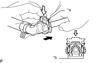
*a Retainer *b Claw Push Push in Connect the fuel lines and push in the retainer to engage the 2 claws. Check that the fuel pipe and fuel tube connector are securely connected by pulling on them.
-
Inspect for fuel leaks.
-
-
-
FUEL INJECTOR ASSEMBLY
-
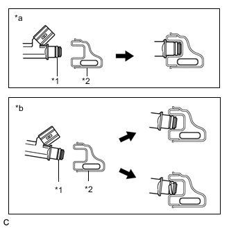
*1 O-ring *2 Fuel Delivery Pipe Sub-assembly *a Correct *b Incorrect Observe the following precautions when removing and installing the fuel injector assemblies:
-
Do not reuse the O-ring or injector vibration insulator.
-
When placing a new O-ring onto the fuel injector assembly, do not damage the O-ring.
-
Coat a new O-ring with gasoline or spindle oil before installing it.
Note
Do not use engine oil, gear oil or brake fluid.
-
-
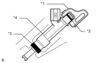
*1 Fuel Delivery Pipe Sub-assembly *2 O-ring *3 Injector Vibration Insulator *4 Fuel Injector Assembly Install the fuel injector assembly into the fuel delivery pipe sub-assembly and cylinder head sub-assembly as shown in the illustration.
Note
Apply gasoline or spindle oil to the contact surfaces of the fuel delivery pipe sub-assembly and fuel injector assembly before installing it.
-
-
FUEL SUCTION TUBE WITH PUMP AND GAUGE ASSEMBLY
Note
Do not disconnect the tube shown in the illustration when disassembling the fuel suction tube with pump and gauge assembly. Doing so will cause reassembly of the fuel suction tube with pump and gauge assembly to be impossible as the tube is pressed into the No. 1 plate sub-assembly.
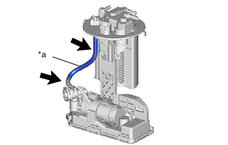
*a Tube -
INSPECT FOR FUEL LEAK
-
Check that there are no fuel leaks from the fuel system after doing any maintenance or repairs.
-