FRONT SUSPENSION MEMBER INSTALLATION
PROCEDURE
INSTALL FRONT STABILIZER BAR
INSTALL FRONT SUSPENSION MEMBER BRACE
TEMPORARILY TIGHTEN FRONT LOWER NO. 1 SUSPENSION ARM SUB-ASSEMBLY LH
Temporarily tighten the front lower No. 1 suspension arm sub-assembly LH to the front suspension crossmember sub-assembly with the 2 bolts and nut.
Note:Because the nut has its own stopper, do not turn the nut. Tighten the bolt with the nut secured.
TEMPORARILY TIGHTEN FRONT LOWER NO. 1 SUSPENSION ARM SUB-ASSEMBLY RH
Tip:Perform the same procedure as the LH side.
INSTALL STEERING LINK ASSEMBLY
INSTALL FRONT CROSS MEMBER SUB-ASSEMBLY
Using a jack and wooden blocks, support the engine and transaxle assembly.
Install the front cross member sub-assembly with the 4 bolts.
99 N*m
1010 kgf*cm
73 ft.*lbf
Connect the front engine mounting insulator to the front cross member sub-assembly with the 2 bolts.
95 N*m
969 kgf*cm
70 ft.*lbf
INSTALL FRONT SUSPENSION CROSSMEMBER SUB-ASSEMBLY
Support the front suspension crossmember sub-assembly with an engine lifter using 4 attachments or equivalent tools.
CAUTION:The front suspension crossmember sub-assembly is a heavy component. Make sure that it is supported securely.
Make sure to secure the front suspension crossmember sub-assembly to prevent it from dropping.
Note:Use the attachments to keep the front suspension crossmember sub-assembly level.
Uniformly tighten 2 bolts while alternately inserting SST into the left and right side reference holes in the front suspension crossmember sub-assembly.
09670-00020
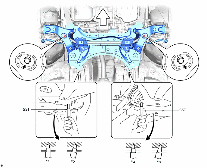
*a
OK
*b
NG

Front of the Vehicle
-
-
137 N*m
1397 kgf*cm
101 ft.*lbf
Lower the engine lifter.
Connect the rear engine mounting insulator to the front suspension crossmember sub-assembly with the 2 bolts and 2 nuts.
95 N*m
969 kgf*cm
70 ft.*lbf
for 1ZR-FAE, 1AD-FTV:
Install the 2 wiring harness clamp brackets with the 2 bolts.
12.5 N*m
127 kgf*cm
9 ft.*lbf
INSTALL FRONT SUSPENSION MEMBER REAR BRACE LH
-
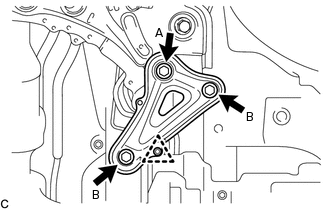
Type A:
Install the front suspension member rear brace LH with the 2 bolts (B) and bolt (A).
Bolt A
137 N*m
1397 kgf*cm
101 ft.*lbf
Bolt B
93 N*m
948 kgf*cm
69 ft.*lbf
Install the clip.
-
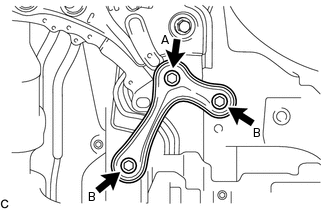
Type B:
Install the front suspension member rear brace LH with the 2 bolts (B) and bolt (A).
Bolt A
137 N*m
1397 kgf*cm
101 ft.*lbf
Bolt B
93 N*m
948 kgf*cm
69 ft.*lbf
-
INSTALL FRONT SUSPENSION MEMBER REAR BRACE RH
Tip:Perform the same procedure as the LH side.
INSTALL FRONT SUSPENSION MEMBER REINFORCEMENT LH
-
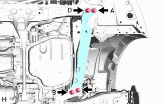
Install the front suspension member reinforcement LH with the 4 bolts.
99 N*m
1010 kgf*cm
73 ft.*lbf
Note:Temporarily tighten the bolt (A) and bolt (B), and then fully tighten the 4 bolts in the order of C, B, D and A.
-
INSTALL FRONT SUSPENSION MEMBER REINFORCEMENT RH
-
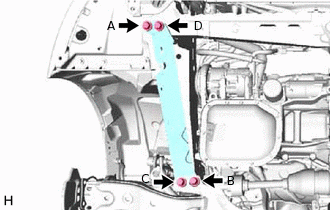
Install the front suspension member reinforcement RH with the 4 bolts.
99 N*m
1010 kgf*cm
73 ft.*lbf
Note:Temporarily tighten the bolt (A) and bolt (B), and then fully tighten the 4 bolts in the order of C, B, D and A.
-
INSTALL FRONT ENGINE MOUNTING BRACKET LOWER REINFORCEMENT (w/ Reinforcement)
Install the front engine mounting bracket lower reinforcement with the 2 bolts.
99 N*m
1010 kgf*cm
73 ft.*lbf
CONNECT FRONT LOWER NO. 1 SUSPENSION ARM SUB-ASSEMBLY LH
CONNECT FRONT LOWER NO. 1 SUSPENSION ARM SUB-ASSEMBLY RH
Tip:Perform the same procedure as the LH side.
CONNECT TIE ROD END SUB-ASSEMBLY LH
CONNECT TIE ROD END SUB-ASSEMBLY RH
Tip:Perform the same procedure as the LH side.
INSTALL FRONT STABILIZER LINK ASSEMBLY LH
Install the front stabilizer link assembly LH to the front stabilizer bar with the nut.
74 N*m
755 kgf*cm
55 ft.*lbf
Note:Do not damage the boot of the ball joint.
Tip:If the ball joint turns together with the nut, use a 6 mm hexagon wrench to hold the stud bolt.
INSTALL FRONT STABILIZER LINK ASSEMBLY RH
Tip:Perform the same procedure as the LH side.
CONNECT NO. 1 STEERING COLUMN HOLE COVER SUB-ASSEMBLY
CONNECT NO. 2 STEERING INTERMEDIATE SHAFT ASSEMBLY
INSTALL COLUMN HOLE COVER SILENCER SHEET
INSTALL FRONT WHEELS
103 N*m
1050 kgf*cm
76 ft.*lbf
STABILIZE SUSPENSION
FULLY TIGHTEN FRONT LOWER NO. 1 SUSPENSION ARM SUB-ASSEMBLY LH
FULLY TIGHTEN FRONT LOWER NO. 1 SUSPENSION ARM SUB-ASSEMBLY RH
Tip:Perform the same procedure as the LH side.
INSTALL REAR ENGINE UNDER COVER LH
INSTALL REAR ENGINE UNDER COVER RH
INSTALL FRONT NO. 3 ENGINE UNDER COVER (for Full Cover Type)
INSTALL CENTER NO. 4 ENGINE UNDER COVER (w/ Cover)
INSTALL NO. 1 ENGINE UNDER COVER
INSTALL FRONT LOWER BUMPER ABSORBER
INSPECT AND ADJUST FRONT WHEEL ALIGNMENT