SFI SYSTEM(w/ Canister Pump Module), Diagnostic DTC:P24D511, P2B7A11
| DTC Code | DTC Name |
|---|---|
| P24D511 | EVAP System Pressure Sensor/Switch "B" Circuit Low Circuit Short to Ground |
| P2B7A11 | EVAP System Pressure Sensor/Switch "C" Circuit Low Circuit Short to Ground |
DESCRIPTION
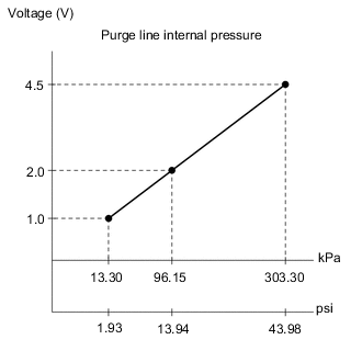
The No. 2 turbo pressure sensor is installed between the No. 1 check valve and intake manifold and converts the purge pipe internal pressure into electrical signals, which it outputs to the ECM.
| DTC No. | Detection Item | DTC Detection Condition | Trouble Area | MIL | Memory | Note |
|---|---|---|---|---|---|---|
| P24D511 | EVAP System Pressure Sensor/Switch "B" Circuit Low Circuit Short to Ground | The output voltage from the No. 2 turbo pressure sensor (bank 1) is below 0.97 V for 3 seconds or more (2 trip detection logic). |
|
Comes on | DTC stored | SAE: P24D7 |
| P2B7A11 | EVAP System Pressure Sensor/Switch "C" Circuit Low Circuit Short to Ground | The output voltage from the No. 2 turbo pressure sensor (bank 2) is below 0.97 V for 3 seconds or more (2 trip detection logic). |
|
Comes on | DTC stored | SAE: P2B7C |
Tech Tips
When a DTC is output, check the Data List item "Purge Pressure Sensor Bank1 and Purge Pressure Sensor Bank2" using the GTS.
| DTC No. | Purge Pressure Sensor Bank1 or Purge Pressure Sensor Bank2 | Malfunction |
|---|---|---|
| P24D511 | Approximately 0 kPa [0 psi] |
|
| P2B7A11 |
|
If the Data List displays a normal value, the normal value may be due to a temporary recovery from the malfunction condition. Check for intermittent problems.
MONITOR DESCRIPTION
The ECM calculates the purge line internal pressure from the No. 2 turbo pressure sensor output voltage. If the No. 2 turbo pressure sensor output voltage is not within the normal range, there may be a malfunction in the No. 2 turbo pressure sensor or an open or short circuit. In this case, the ECM illuminates the MIL and stores a DTC.
Example:
When the sensor output voltage is below 0.97 V for 3 seconds or more, the ECM stores a DTC.
MONITOR STRATEGY
| Required Sensors/Components | No. 2 turbo pressure sensor |
| Frequency of Operation | Continuous |
CONFIRMATION DRIVING PATTERN
-
Connect the GTS to the DLC3.
-
Turn the engine switch on (IG) and turn the GTS on.
-
Clear the DTCs (even if no DTCs are stored, perform the clear DTC procedure).
-
Turn the engine switch off and wait for at least 30 seconds.
-
Turn the engine switch on (IG).
-
Turn the GTS on.
-
Start the engine and wait 5 seconds or more.
-
Enter the following menus: Powertrain / Engine / Trouble Codes.
-
Read the pending DTCs.
Tech Tips
-
If a pending DTC is output, the system is malfunctioning.
-
If a pending DTC is not output, perform the following procedure.
-
-
Enter the following menus: Powertrain / Engine / Utility / All Readiness.
-
Input the DTC: P24D511 or P2B7A11.
-
Check the DTC judgment result.
GTS Display Description NORMAL
-
DTC judgment completed
-
System normal
ABNORMAL
-
DTC judgment completed
-
System abnormal
INCOMPLETE
-
DTC judgment not completed
-
Perform driving pattern after confirming DTC enabling conditions
Tech Tips
-
If the judgment result shows NORMAL, the system is normal.
-
If the judgment result shows ABNORMAL, the system has a malfunction.
-
WIRING DIAGRAM
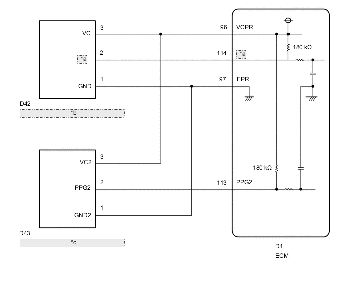
| *a | PPG |
| *b | No. 2 Turbo Pressure Sensor (Bank 1) |
| *c | No. 2 Turbo Pressure Sensor (Bank 2) |
CAUTION / NOTICE / HINT
Tech Tips
-
Read Freeze Frame Data using the GTS. The ECM records vehicle and driving condition information as Freeze Frame Data the moment a DTC is stored. When troubleshooting, Freeze Frame Data can help determine if the vehicle was moving or stationary, if the engine was warmed up or not, if the air fuel ratio was lean or rich, and other data from the time the malfunction occurred.
-
Bank 1 refers to the bank that includes the No. 1 cylinder*.
*: The No. 1 cylinder is the cylinder which is farthest from the transmission.
-
Bank 2 refers to the bank that does not include the No. 1 cylinder.
DTC Suspected Area P24D511 Bank 1 P2B7A11 Bank 2
PROCEDURE
-
CHECK HARNESS AND CONNECTOR
Tech Tips
Make sure that the connector is properly connected. If it is not, securely connect it and check for DTCs again.
-
Disconnect the No. 2 turbo pressure sensor connector.
-
Turn the engine switch on (IG).
-
Measure the voltage according to the value(s) in the table below.
Standard Voltage Tester Connection Condition Specified Condition D42-3 (VC) - D42-1 (GND) Engine switch on (IG) 4.5 to 5.5 V D43-3 (VC2) - D43-1 (GND2) Engine switch on (IG) 4.5 to 5.5 V D42-2 (PPG) - D42-1 (GND) Engine switch on (IG) 3.0 to 5.5 V D43-2 (PPG2) - D43-1 (GND2) Engine switch on (IG) 3.0 to 5.5 V -
Turn the engine switch off and wait for at least 30 seconds.
-
Measure the resistance according to the value(s) in the table below.
Standard Resistance Tester Connection Condition Specified Condition D42-3 (VC) - D42-2 (PPG) Engine switch off 171 to 189 kΩ D43-3 (VC2) - D43-2 (PPG2) Engine switch off 171 to 189 kΩ Result Proceed to OK NG
OK 
REPLACE NO. 2 TURBO PRESSURE SENSOR Click here
NG 
-
-
CHECK HARNESS AND CONNECTOR (NO. 2 TURBO PRESSURE SENSOR - ECM)
-
Disconnect the No. 2 turbo pressure sensor connector.
-
Disconnect the ECM connector.
-
Measure the resistance according to the value(s) in the table below.
Standard Resistance Tester Connection Condition Specified Condition D42-3 (VC) - D1-96 (VCPR) Always Below 1 Ω D43-3 (VC2) - D1-96 (VCPR) Always Below 1 Ω D42-2 (PPG) or D1-114 (PPG) - Body ground and other terminals Always 10 kΩ or higher D43-2 (PPG2) or D1-113 (PPG2) - Body ground and other terminals Always 10 kΩ or higher Result Proceed to OK NG
OK
REPLACE ECM Click here
NG
REPAIR OR REPLACE HARNESS OR CONNECTOR
-