VEHICLE STABILITY CONTROL SYSTEM TRC OFF Indicator Light does not Come ON
DESCRIPTION
Refer to TRC OFF Indicator Light Remains ON Click here.
WIRING DIAGRAM
Refer to VSC OFF Indicator Light Remains ON Click here.
INSPECTION PROCEDURE
Note
-
After replacing the brake actuator assembly, perform calibration Click here.
-
Before disconnecting the connector, make sure that there are no problems with the connection.
-
After disconnecting the connector, make sure that the connector case and terminals are not deformed or corroded.
PROCEDURE
-
CHECK IF SKID CONTROL ECU CONNECTOR IS SECURELY CONNECTED
-
Check if the skid control ECU (brake actuator assembly) connector is securely connected.
OK The connector is securely connected.
NG 
CONNECT CONNECTOR TO ECU CORRECTLY
OK 
-
-
CHECK TERMINAL VOLTAGE (IG1 TERMINAL)
-
Turn the ignition switch off.
-
Disconnect the skid control ECU (brake actuator assembly) connector.
-
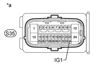
Text in Illustration *a Front view of wire harness connector
(to Skid Control ECU [Brake Actuator Assembly])
Measure the voltage according to the value(s) in the table below.
Standard Voltage Tester Connection Switch Condition Specified Condition S35-34 (IG1) - Body ground Ignition switch ON 11 to 14 V
NG
REPAIR OR REPLACE HARNESS OR CONNECTOR
OK
-
-
CHECK HARNESS AND CONNECTOR (GND1 TERMINAL)
-
Turn the ignition switch off.
-
Disconnect the skid control ECU (brake actuator assembly) connector.
-
Measure the resistance according to the value(s) in the table below.
Standard Resistance Tester Connection Condition Specified Condition S35-1 (GND1) - Body ground Always Below 1 Ω
NG
REPAIR OR REPLACE HARNESS OR CONNECTOR
OK
-
-
INSPECT VSC OFF SWITCH
-
Turn the ignition switch off.
-
Remove the VSC OFF switch Click here.
-
Inspect the VSC OFF switch Click here.
NG
REPLACE VSC OFF SWITCH Click here
OK
-
-
CHECK HARNESS AND CONNECTOR (SKID CONTROL ECU - VSC OFF SWITCH)
-
Turn the ignition switch off.
-
Disconnect the VSC OFF switch connector.
-
Disconnect the skid control ECU (brake actuator assembly) connector.
-
Measure the resistance according to the value(s) in the table below.
Standard Resistance Tester Connection Condition Specified Condition S35-30 (CSW) - V8-3 Always Below 1 Ω S35-30 (CSW) - Body ground Always 10 kΩ or higher V8-4 - Body ground Always Below 1 Ω
NG
REPAIR OR REPLACE HARNESS OR CONNECTOR
OK
-
-
CHECK HARNESS AND CONNECTOR (SKID CONTROL ECU - COMBINATION METER)
-
Turn the ignition switch off.
-
Disconnect the skid control ECU (brake actuator assembly) connector.
-
Disconnect the C26 combination meter connector.
-
Measure the resistance according to the value(s) in the table below.
Standard Resistance Tester Connection Condition Specified Condition S35-23 (INFR) - C26-21 Always Below 1 Ω S35-23 (INFR) - Body ground Always 10 kΩ or higher
NG
REPAIR OR REPLACE HARNESS OR CONNECTOR
OK
-
-
INSPECT COMBINATION METER ASSEMBLY
-
Turn the ignition switch off.
-
Disconnect the skid control ECU (brake actuator assembly) connector.
-
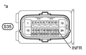
Text in Illustration *a Front view of wire harness connector
(to Skid Control ECU [Brake Actuator Assembly])
Measure the voltage according to the value(s) in the table below.
Standard Voltage Tester Connection Switch Condition Specified Condition S35-23 (INFR) - Body ground Ignition switch ON 11 to 14 V Result Result Proceed to NG A OK for LHD B for RHD C
B
REPLACE BRAKE ACTUATOR ASSEMBLY Click here
C
REPLACE BRAKE ACTUATOR ASSEMBLY Click here
A 
GO TO METER / GAUGE SYSTEM (HOW TO PROCEED WITH TROUBLESHOOTING) Click here
-