FUEL SENDER GAUGE ASSEMBLY(for AWD) REMOVAL

CAUTION / NOTICE / HINT
The necessary procedures (adjustment, calibration, initialization or registration) that must be performed after parts are removed and installed, or replaced during fuel sender gauge assembly or No. 2 fuel sender gauge assembly removal/installation are shown below.
| Replaced Part or Performed Procedure | Necessary Procedure | Effect/Inoperative Function when Necessary Procedure not Performed | Link |
|---|---|---|---|
| Disconnect cable from negative battery terminal | Memorize steering angle neutral point | Lane departure alert system (w/ Steering Control) | |
| Simple intelligent parking assist system*1 | |||
| Toyota parking assist-sensor system (w/ Simple Intelligent Parking Assist System)*1 | |||
| Pre-collision system | |||
| Initialize back door lock | Power door lock control system | ||
| Drive the vehicle until stop and start control is permitted (approximately 5 to 60 minutes)*2 | Stop and start system |
-
*1: When performing learning using the GTS.
-
*2: w/ Stop and start system
CAUTION:
-
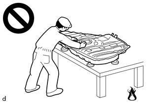
Never perform work on fuel system components near any possible ignition sources.
-
Vaporized fuel could ignite, resulting in a serious accident.
-
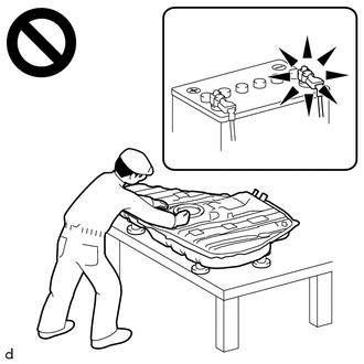
Do not perform work on fuel system components without first disconnecting the cable from the negative (-) battery terminal.
-
Sparks could cause vaporized fuel to ignite, resulting in a serious accident.
PROCEDURE
-
REMOVE FUEL SUCTION TUBE WITH PUMP AND GAUGE ASSEMBLY
-
REMOVE FUEL SENDER GAUGE ASSEMBLY
-
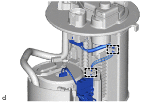
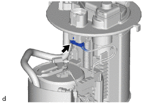
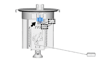
Disengage the 2 clamps to disconnect the wire harness.
Note
Do not damage the wire harness.
-
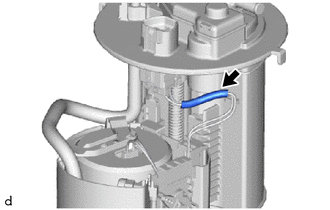
Remove the harness protector from the wire harness.
Note
Do not damage the wire harness.
-
Disconnect the fuel sender gauge assembly connector.
-
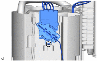
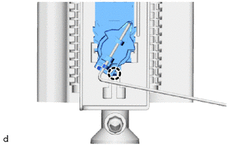
Disengage the claw to remove the fuel sender gauge assembly from the fuel suction tube with pump and gauge assembly.
Note
Be careful not to bend the arm of the fuel sender gauge assembly.
-
-
REMOVE REAR FLOOR SERVICE HOLE COVER RH
-
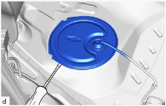
Using a clip remover with its tip wrapped with protective tape, remove the rear floor service hole cover and butyl tape.
-
Disconnect the fuel return vent tube sub-assembly connector.
-
-
REMOVE FUEL PUMP GAUGE RETAINER
Tech Tips
Perform the same procedure as for the fuel suction tube with pump and gauge assembly.
-
REMOVE FUEL TANK VENT TUBE ASSEMBLY
-
Disconnect the fuel return vent tube sub-assembly and remove the fuel tank vent tube assembly from the fuel tank assembly.
Note
Be careful not to bend the arm of the fuel sender gauge assembly.
-
Remove the fuel suction tube set gasket from the fuel tank assembly.
-
-
REMOVE NO. 2 FUEL SENDER GAUGE ASSEMBLY
-
Disengage the 2 clamps to disconnect the wire harness.
Note
Do not damage the wire harness.
-
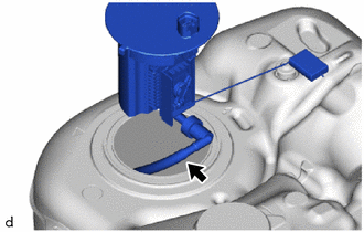
Disconnect the No. 2 fuel sender gauge assembly connector.
-
Disengage the claw to remove the No. 2 fuel sender gauge assembly from the fuel tank vent tube assembly.
Note
Be careful not to bend the arm of the fuel sender gauge assembly.
-