PRE-COLLISION SYSTEM, Diagnostic DTC:U1002
| DTC Code | DTC Name |
|---|---|
| U1002 | Lost Communication with Gateway Module |
DESCRIPTION
| DTC No. | Detection Item | DTC Detection Condition | Trouble Area |
|---|---|---|---|
| U1002 | Lost Communication with Gateway Module | When the ignition switch to ON, a communication error between the forward recognition camera and millimeter wave radar sensor assembly is detected for approximately 0.3 seconds. |
|
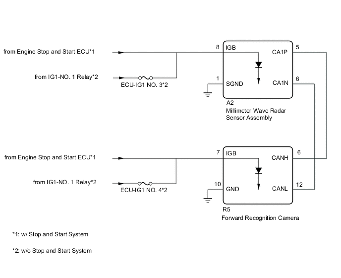
WIRING DIAGRAM
CAUTION / NOTICE / HINT
Note
-
w/o Stop and Start System:
Inspect the fuses for circuits related to this system before performing the following inspection procedure.
-
Before measuring the resistance of the CAN bus, turn the ignition switch off and leave the vehicle for 1 minute or more without operating the key or any switches, or opening or closing the doors. After that, disconnect the cable from the negative (-) battery terminal and leave the vehicle for 1 minute or more before measuring the resistance.
-
After turning the ignition switch off, waiting time may be required before disconnecting the cable from the negative (-) battery terminal. Therefore, make sure to read the disconnecting the cable from the negative (-) battery terminal notices before proceeding with work.
-
If the forward recognition camera has been replaced with a new one, be sure to perform Forward Recognition Axis Adjustment.
-
When the millimeter wave radar sensor assembly is replaced with a new one, adjustment of the radar sensor beam axis must be performed.
Tech Tips
-
Operating the ignition switch, any other switches or a door triggers related ECUs and sensors to communicate using the CAN communication system. This communication will cause the resistance value to change.
-
Even after DTCs are cleared, if a DTC is stored again after driving the vehicle for a while, the malfunction may be occurring due to vibration of the vehicle. In such a case, wiggling the connectors of ECUs or wire harnesses while performing the inspection below may help determine the cause of the malfunction.
PROCEDURE
-
CHECK FOR DTCs (PRE-COLLISION SYSTEM)
-
Check for DTCs.
Body Electrical > Pre-Collision 2 > Trouble CodesResult Result Proceed to DTC U023A and/or U1002 and other DTCs are output A Only DTC U023A and/or U1002 is output B
A 
GO TO DIAGNOSTIC TROUBLE CODE CHART Click here
B 
-
-
CHECK FOR OPEN IN CAN BUS SAB LINES (FORWARD RECOGNITION CAMERA)
-
Disconnect the cable from the negative (-) battery terminal.
-
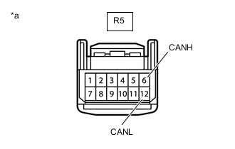
*a Front view of wire harness connector
(to Forward Recognition Camera)
Disconnect the forward recognition camera connector.
-
Measure the resistance according to the value(s) in the table below.
Standard Resistance Tester Connection Condition Specified Condition R5-6 (CANH) - R5-12 (CANL) Cable disconnected from negative (-) battery terminal 108 to 132 Ω -
Connect the forward recognition camera connector.
Result Proceed to OK NG
NG
REPAIR OR REPLACE CAN BUS SAB LINE OR CONNECTOR (FORWARD RECOGNITION CAMERA - MILLIMETER WAVE RADAR SENSOR ASSEMBLY)
OK
-
-
CHECK HARNESS AND CONNECTOR (POWER SOURCE VOLTAGE (FORWARD RECOGNITION CAMERA))
-
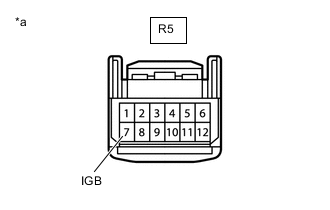
*a Front view of wire harness connector
(to Forward Recognition Camera)
Disconnect the forward recognition camera connector.
-
Connect the cable to the negative (-) battery terminal.
-
Measure the voltage according to the value(s) in the table below.
Standard Voltage Tester Connection Switch Condition Specified Condition R5-7 (IGB) - Body ground Ignition switch ON 11 to 14 V*1
10.5 to 16 V*2
-
*1: w/o Stop and Start System
-
*2: w/ Stop and Start System
-
-
Connect the forward recognition camera connector.
Result Result Proceed to OK A NG (w/o Stop and Start System) B NG (w/ Stop and Start System) C
B
REPAIR OR REPLACE HARNESS OR CONNECTOR (POWER SOURCE CIRCUIT)
C
INSPECT STOP AND START SYSTEM (BACKUP BOOST CONVERTER CIRCUIT) Click here
A
-
-
CHECK HARNESS AND CONNECTOR (FORWARD RECOGNITION CAMERA - BODY GROUND)
-
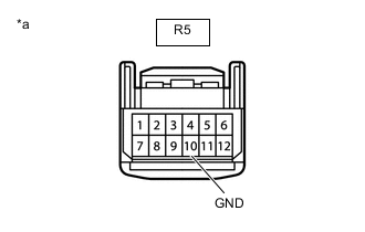
*a Front view of wire harness connector
(to Forward Recognition Camera)
Disconnect the forward recognition camera connector.
-
Measure the resistance according to the value(s) in the table below.
Standard Resistance Tester Connection Condition Specified Condition R5-10 (GND) - Body ground Always Below 1 Ω -
Connect the forward recognition camera connector.
Result Proceed to OK NG
NG
REPAIR OR REPLACE HARNESS OR CONNECTOR
OK
-
-
CHECK HARNESS AND CONNECTOR (POWER SOURCE VOLTAGE (MILLIMETER WAVE RADAR SENSOR ASSEMBLY))
-
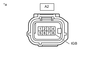
*a Front view of wire harness connector
(to Millimeter Wave Radar Sensor Assembly)
Disconnect the millimeter wave radar sensor assembly connector.
-
Measure the voltage according to the value(s) in the table below.
Standard Voltage Tester Connection Switch Condition Specified Condition A2-8 (IGB) - Body ground Ignition switch ON 11 to 14 V*1
10.5 to 16 V*2
-
*1: w/o Stop and Start System
-
*2: w/ Stop and Start System
-
-
Connect the millimeter wave radar sensor assembly connector.
Result Result Proceed to OK A NG (w/o Stop and Start System) B NG (w/ Stop and Start System) C
B
REPAIR OR REPLACE HARNESS OR CONNECTOR (POWER SOURCE CIRCUIT)
C
INSPECT STOP AND START SYSTEM (BACKUP BOOST CONVERTER CIRCUIT) Click here
A
-
-
CHECK HARNESS AND CONNECTOR (MILLIMETER WAVE RADAR SENSOR ASSEMBLY - BODY GROUND)
-
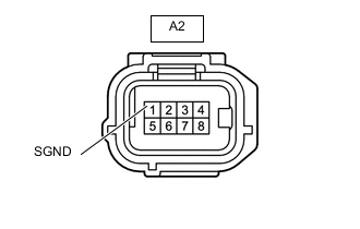
*a Front view of wire harness connector
(to Millimeter Wave Radar Sensor Assembly)
Disconnect the millimeter wave radar sensor assembly connector.
-
Measure the resistance according to the value(s) in the table below.
Standard Resistance Tester Connection Condition Specified Condition A2-1 (SGND) - Body ground Always Below 1 Ω -
Connect the millimeter wave radar sensor assembly connector.
Result Proceed to OK NG
NG
REPAIR OR REPLACE HARNESS OR CONNECTOR
OK
-
-
REPLACE FORWARD RECOGNITION CAMERA
-
Replace the forward recognition camera.
-
Perform Forward Recognition Axis Adjustment.
Result Proceed to NEXT
NEXT
-
-
CHECK FOR DTCs (PRE-COLLISION SYSTEM)
-
Clear the DTCs.
Body Electrical > Pre-Collision 2 > Clear DTCs -
Make sure that the DTC detection conditions are met.
Tech Tips
If the detection conditions are not met, the system cannot detect the malfunction.
-
Check for DTCs.
Body Electrical > Pre-Collision 2 > Trouble CodesResult Result Proceed to DTC U023A is not output A DTC U023A is output B
A
END (FORWARD RECOGNITION CAMERA WAS DEFECTIVE)
B
-
-
REPLACE MILLIMETER WAVE RADAR SENSOR ASSEMBLY
-
Replace the millimeter wave radar sensor assembly.
-
Adjust the millimeter wave radar sensor assembly.
Result Proceed to NEXT
NEXT
-
-
CLEAR DTC (PRE-COLLISION SYSTEM)
-
Clear the DTCs.
Body Electrical > Pre-Collision 2 > Clear DTCsResult Proceed to NEXT
NEXT
END (MILLIMETER WAVE RADAR SENSOR ASSEMBLY WAS DEFECTIVE)
-